Difference between revisions of "Heatweb BEMS Hat"
| (32 intermediate revisions by the same user not shown) | |||
| Line 1: | Line 1: | ||
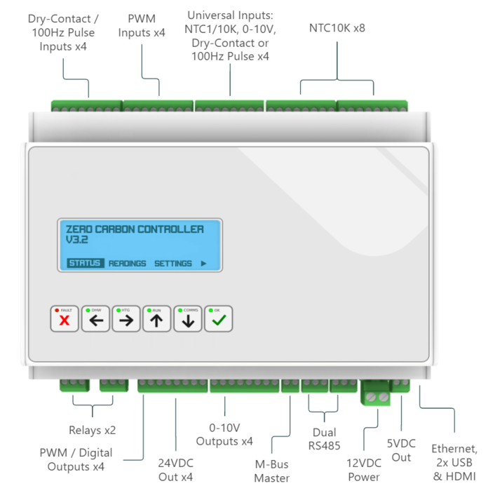
[[File: | [[File:Zccfront3.PNG|right|frameless|703x703px]] | ||
[[Category:Hardware]] | [[Category:Hardware]] | ||
{| class="wikitable" | {| class="wikitable" | ||
|+ | |+ | ||
! | !Feature | ||
! | !Specifcations | ||
|- | |||
| | |||
Controller compatibility: | |||
| | |||
Raspberry Pi, all models<br> | |||
Beaglebone Black<br> | |||
ESP32<br> | |||
None (stand alone Modbus Slave Mode) | |||
|- | |||
|Controller interface: | |||
| | |||
Raspberry Pi header<br> | |||
I2C communications to controller<br> | |||
3x UARTs<br> | |||
5V power to controller<br> | |||
External watchdog to controller | |||
|- | |- | ||
|8 x thermistor inputs | |8 x thermistor inputs | ||
| Line 12: | Line 28: | ||
|4 x universal inputs | |4 x universal inputs | ||
| | | | ||
100Hz pulse signals<br> | DIP selected mode<br> | ||
100Hz pulse signals (count and frequency)<br> | |||
volt-free contacts<br> | volt-free contacts<br> | ||
0-10V signals<br> | 0-10V signals<br> | ||
| Line 20: | Line 37: | ||
| | | | ||
100Hz pulse signals<br> | 100Hz pulse signals<br> | ||
volt-free contacts | volt-free contacts<br> | ||
State, counter and frequency readings | |||
|- | |||
|4 x PWM inputs | |||
| | |||
DIP selected pull-up resistors (5V)<br> | |||
Voltage comparator<br> | |||
Low state: < 3V<br> | |||
High state: 3V to 24V | |||
|- | |||
|4 x Digital PWM outputs | |||
| | |||
Pull-down operation<br> | |||
DIP selected pull-up resistors (5V/24V)<br> | |||
Diode protection for connection to relays | |||
|- | |||
|4 x 0-10v outputs | |||
|10mA peak current | |||
|- | |- | ||
|2 x change-over relays | |2 x change-over relays | ||
|10A @ 36V | |10A @ 36V | ||
|- | |- | ||
| | |2 x RS485 | ||
| | |||
Independent lines for Modbus or bespoke protocols<br> | |||
DIP switch selectable terminating resistors<br> | |||
One line DIP switchable for Modbus Slave Mode | |||
|- | |||
|1 x M-Bus | |||
| | |||
For meter communications<br> | |||
On-board supply: 36V @ 30mA<br> | |||
Short-circuit protection<br> | |||
Device limit: 10 | |||
|- | |||
|Power Supply | |||
| | |||
Nominal voltage: 12VDC<br> | |||
Current requirement: 3A<br> | |||
Minimum supply voltage: 11.8V<br> | |||
Peak supply voltage: 16V | |||
|- | |||
|Battery support | |||
| | | | ||
On-board rechargeable battery socket<br> | |||
Voltage | Maintains power to all systems (5V, 24V & 36V) during loss of supply<br> | ||
< | Voltage monitoring with safe shutdown<br> | ||
Duration: > 1 hour (can be extended with use of sleep mode)<br> | |||
Battery: 18650 Lithium-ion Rechargeable Cell - 2500mAh 3.7V 20A | |||
|- | |||
|Real time clock | |||
|Battery:CR2450 Coin Cell | |||
|- | |- | ||
|General purpose input button | |||
| | | | ||
|- | |||
|3 x user definable LEDs | |||
| | | | ||
|- | |- | ||
|Fan control and connector | |||
| | | | ||
|- | |||
|Dimensions | |||
| | | | ||
Length:<br> | |||
Width:<br> | |||
Height: | |||
|} | |} | ||
== About == | |||
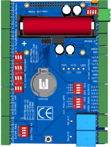
The Heatweb BEMS Hat runs from a 12v dc supply, generating 5v for the board, 24v for valves, and 36v for M-Bus, using on-board dc-dc converters backed up by a rechargeable battery. A coin cell is used to power a real-time clock. | The Heatweb BEMS Hat runs from a 12v dc supply, generating 5v for the board, 24v for valves, and 36v for M-Bus, using on-board dc-dc converters backed up by a rechargeable battery. A coin cell is used to power a real-time clock. | ||
| Line 83: | Line 117: | ||
The battery backup allows us to safely shut-down all valves and the controls when power is removed. This overcomes a common problem with HVAC systems, where valves typically remain open, destroying network performance. | The battery backup allows us to safely shut-down all valves and the controls when power is removed. This overcomes a common problem with HVAC systems, where valves typically remain open, destroying network performance. | ||
[[File:Zero Carbon Controller Summary.pdf|none|thumb]] | |||
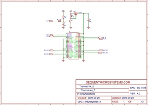
== Schematic == | |||
[[File:THERMAL-Controller-V4 0-SCH.pdf|none|thumb]] | |||
== Images == | |||
<gallery widths="450" heights="300"> | |||
File:Plumbingcontrollerv3b.png | |||
File:Heatweb BEMS Assembly V3 + Pi iso3.png | |||
File:Cm4-io-base-a-3.png|Raspberry Pi Compute CM4 Base Board | |||
</gallery><gallery widths="444" heights="333"> | |||
File:Heatweb BEMS enclosure assembly4.png | |||
File:Heatweb BEMS enclosure assembly3.png | |||
File:Heatweb BEMS enclosure assembly2.png | |||
File:Heatweb BEMS enclosure assembly1.png | |||
File:Heatweb BEMS enclosure assembly.png | |||
File:Heatweb BEMS enclosure assembly Sectional View.jpg | |||
File:Heatweb BEMS enclosure assembly RC2.png | |||
File:Heatweb BEMS enclosure assembly RC1.png | |||
</gallery> | |||
== Resources == | |||
* https://github.com/heatweb/plumbing-controller | |||
* https://github.com/SequentMicrosystems/ti-rpi/ | |||
* [https://github.com/SequentMicrosystems/ti-rpi/blob/main/MODBUS.md Modbus Registers] | |||
* [https://www.waveshare.com/cm4-io-base-a.htm Waveshare CM4-IO-BASE-A] | |||
* [https://www.waveshare.com/wiki/CM4-IO-BASE-A Waveshare CM4-IO-BASE-A Wiki] | |||
* [[Wiring Diagrams]] | |||
* [[Wiring Editor]] | |||
Latest revision as of 14:10, 7 November 2022
| Feature | Specifcations |
|---|---|
|
Controller compatibility: |
Raspberry Pi, all models |
| Controller interface: |
Raspberry Pi header |
| 8 x thermistor inputs |
10k resistance temperature devices |
| 4 x universal inputs |
DIP selected mode |
| 4 x volt-free / pulse inputs |
100Hz pulse signals |
| 4 x PWM inputs |
DIP selected pull-up resistors (5V) |
| 4 x Digital PWM outputs |
Pull-down operation |
| 4 x 0-10v outputs | 10mA peak current |
| 2 x change-over relays | 10A @ 36V |
| 2 x RS485 |
Independent lines for Modbus or bespoke protocols |
| 1 x M-Bus |
For meter communications |
| Power Supply |
Nominal voltage: 12VDC |
| Battery support |
On-board rechargeable battery socket |
| Real time clock | Battery:CR2450 Coin Cell |
| General purpose input button | |
| 3 x user definable LEDs | |
| Fan control and connector | |
| Dimensions |
Length: |
About
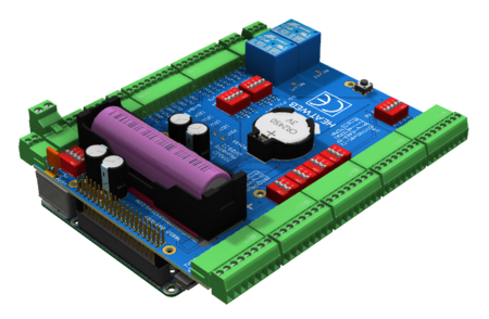
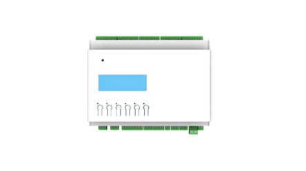
The Heatweb BEMS Hat runs from a 12v dc supply, generating 5v for the board, 24v for valves, and 36v for M-Bus, using on-board dc-dc converters backed up by a rechargeable battery. A coin cell is used to power a real-time clock.
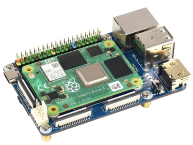
WiFi, Ethernet and Bluetooth are provided by the parent controller board.
A number of the inputs are universal, and can be switched between NTC, 0-10v, or volt-free / pulse inputs (jumper selected). This ability to alter the hardware setup increases versatility significantly.
The addition of M-Bus allows us to connect to heat meters as standard, making the board a stand alone solution to open-sourcing meter data, and to use meter data within control logic.
The battery backup allows us to safely shut-down all valves and the controls when power is removed. This overcomes a common problem with HVAC systems, where valves typically remain open, destroying network performance.
Schematic
