Difference between revisions of "Morden Hall"
| (39 intermediate revisions by the same user not shown) | |||
| Line 1: | Line 1: | ||
[[File: | [[File:Mhdash2.PNG|791x791px|right|frameless]]https://www.nationaltrust.org.uk/morden-hall-park | ||
https://www.nationaltrust.org.uk/morden-hall-park | |||
The ‘Livinggreen Project’ was an HLF and EU funded initiative to show how heritage assets can be updated to be highly sustainable. It was implemented in five European cities. Morden Hall Park in South London, with over 750,000 visitors a year, was chosen as the sole UK project. | The ‘Livinggreen Project’ was an HLF and EU funded initiative to show how heritage assets can be updated to be highly sustainable. It was implemented in five European cities. Morden Hall Park in South London, with over 750,000 visitors a year, was chosen as the sole UK project. | ||
| Line 34: | Line 31: | ||
#Generate operational data that shows how the various renewables operate under different weather and load conditions | #Generate operational data that shows how the various renewables operate under different weather and load conditions | ||
== | == The Stable Yard == | ||
<iframe key="wiki" align="right" width="100%" height=" | <iframe key="wiki" align="right" width="100%" height="900" level="" path="/gojs/samples/wiring23.html?cid=heatweb_morden_hall_schematic.json&height=750px&border=none" /> | ||
<pre class="wikidiagrams" style="display:none"> | <pre class="wikidiagrams" style="display:none"> | ||
heatweb_morden_hall_schematic.json Schematic | heatweb_morden_hall_schematic.json Schematic | ||
heatweb_morden_hall_day_1.json First Install 28/09/22 | heatweb_morden_hall_day_1.json First Install 28/09/22 | ||
heatweb_morden_hall_1.json Wiring 1 | |||
heatweb_morden_hall_dashboard_1.json Dashboard 1 | heatweb_morden_hall_dashboard_1.json Dashboard 1 | ||
heatweb_morden_hall_2.json Wiring 2 | heatweb_morden_hall_2.json Wiring 2 | ||
heatweb_morden_hall_schematic_dash.json Schematic Dashboard | |||
</pre> | </pre> | ||
== Site Works 28/09/2022 == | === Site Works 28/09/2022 === | ||
{| class="wikitable" | {| class="wikitable" | ||
|+ | |+Parts Used | ||
!Description | !Description | ||
!Quantity | !Quantity | ||
| Line 71: | Line 68: | ||
| | | | ||
|} | |} | ||
<pre> | <pre> | ||
| Line 119: | Line 114: | ||
Richard. | Richard. | ||
</pre>[[File:Morden48h.png|frameless|1068x1068px]] | </pre>[[File:Morden48h.png|frameless|1068x1068px]] | ||
== System Pressures == | |||
The system has been losing pressure regularly, causing hot water to fail, and as part of the monitoring we have added a pressure sensor to the main system to investigate. | |||
A Grundfos RPS sensor was used, providing both static pressure and temperature signals. It was fitted near the top of Thermal Store 1. | |||
As soon as data became available the reason became clear... the expansion vessel is not functioning, and pressures climb by around a bar during reheat cycles, then drop. On the first heat up following a top-up, water is discharged with nowhere else to go, and then when the store cools at all, pressure drop significantly. | |||
We have added minimum and maximum pressures to the dashboard with a traffic light theme to draw attention to further problems. | |||
As a matter of urgency the expansion vessel requires either a service or replacement. | |||
[[File:Stableyp1.png|frameless|1075x1075px]] | |||
The following graph shows heat pump output temperature in orange and system pressure in blue. | |||
The ability to plot multiple historical metrics side by side is a great advantage in fault finding. | |||
[[File:Stableyp2.png|frameless|1075x1075px]] | |||
== Monitoring Hydro-Electric Archimedes Turbine == | == Monitoring Hydro-Electric Archimedes Turbine == | ||
| Line 131: | Line 145: | ||
One of the clients requests is to add some visibility to the hydro-electric system. This is to include temperature monitoring of the turbine casing, and monitoring the electricity generated. | One of the clients requests is to add some visibility to the hydro-electric system. This is to include temperature monitoring of the turbine casing, and monitoring the electricity generated. | ||
<gallery widths="250" heights=" | <gallery widths="600" heights="350"> | ||
File:Mhturbine.jpg|The Archimedes Turbine at Morden Hall | |||
File:Mhdash1.PNG|Operational Dashboard (in progress) | |||
</gallery> | |||
<gallery widths="250" heights="350"> | |||
File:Mordenhallmeter1.jpg|Electricity meter | File:Mordenhallmeter1.jpg|Electricity meter | ||
File:Mordenturbine.jpg|The generator | File:Mordenturbine.jpg|The generator | ||
File: | File:Archimedes.PNG|Principles of Operation https://onlinelibrary.wiley.com/doi/abs/10.1002/er.6893 | ||
</gallery> | </gallery> | ||
{{#l:MT174-Techical-Description.pdf|Electricity Meter Technical}} | {{#l:MT174-Techical-Description.pdf|Electricity Meter Technical}} | ||
=== Site | === Site Works 07/10/2022 === | ||
The purpose of the visit was to install the control panel, cabling, and get at least one sensor online. | The purpose of the visit was to install the control panel, cabling, and get at least one sensor online. | ||
| Line 150: | Line 169: | ||
A follow up visit will be required to add additional sensors and wire in the pulsed output from the meter. | A follow up visit will be required to add additional sensors and wire in the pulsed output from the meter. | ||
{| class="wikitable" | |||
|+Parts Used | |||
!Description | |||
!Quantity | |||
!Cost | |||
!Notes | |||
|- | |||
|Open Source Control Panel | |||
|1 | |||
| | |||
| | |||
|- | |||
|NTC Pipe Temperature Sensors | |||
|2 | |||
| | |||
| | |||
|- | |||
|2 Core 0.75mm Silicone Cable | |||
|14m | |||
| | |||
| | |||
|} | |||
<gallery widths="250" heights="300"> | <gallery widths="250" heights="300"> | ||
File:Mhwiring2.PNG|Wiring Diagram [https://hwwiki.ddns.net/ui/wiring/wiring22/heatweb_morden_hall_2.json heatweb_morden_hall_2.json] | |||
File:Mhtmeter.jpg|Meter terminals | File:Mhtmeter.jpg|Meter terminals | ||
File:Mhtunit.jpg|Heatweb Controller | File:Mhtunit.jpg|Heatweb Controller | ||
| Line 156: | Line 202: | ||
File:Mhtsensor.jpg|Sensor 1 | File:Mhtsensor.jpg|Sensor 1 | ||
</gallery> | </gallery> | ||
=== Dashboarding === | |||
Following the visit, the data can be seen on the client dashboard. | Following the visit, the data can be seen on the client dashboard. | ||
The graph | <gallery widths="600" heights="270"> | ||
File:Turbineg1.png|Initial data shows the casing temperature against outside air temperature The graph shows the outside air temperature (in blue) and the generator casing temperature (in yellow). After startup the generator temperature can be seen to climb as electricity is generated. | |||
File:Mhdash1.png|A first dashboard is created linking the temperature data to red/green/blue status. The casing temperature changes with air temperature so a better indication is required. | |||
</gallery> | |||
<gallery widths="800" heights="400"> | |||
File:Mhdash3.PNG|Adding a Temperature Rise value, calculated from the difference between the casing temperature and air temperature, gives a far better indication of operation. | |||
</gallery> | |||
=== First Fault (2nd night monitoring) === | |||
It wasn't long before the Archimedes turbine fell over. The events happened overnight, however we have data on the events that may help prevent future occurances. | |||
<gallery widths="650" heights="270"> | |||
File:Archimedesfault1.PNG|A look at the dashboard in the morning gives a clear indication that something is up with the Archimedes turbine. We have RED (indicating overheating) and we have BLUE (indicating it is offline). Note, the offline colour will be changed to YELLOW as it is a warning condition. | |||
File:Archimedesfault1a.PNG|Moving to the Archimedes dashboard screen, we can see the graph of the casing temperatures. At 3am temperatures shoot up, followed by a period of lower output then in the morning it turned off. | |||
</gallery> | |||
== (3) Identifying Problems == | == (3) Identifying Problems == | ||
Latest revision as of 13:34, 11 December 2022
https://www.nationaltrust.org.uk/morden-hall-park
The ‘Livinggreen Project’ was an HLF and EU funded initiative to show how heritage assets can be updated to be highly sustainable. It was implemented in five European cities. Morden Hall Park in South London, with over 750,000 visitors a year, was chosen as the sole UK project.
The site achieved a BREEAM ‘Excellent’ award, however the true potential of the installation has never been fully realised and is in need of some TLC.
At Thermal Integration we were responsible for the original hydraulic design of the system, based on the use of thermal stores and unvented storage to pull all heat sources and loads together as efficiently as possible.
Following ten years of declining performance, the National Trust has agreed to allow us to revisit the installation with a view to realising its original potential, to understand where things went wrong, and to learn from their experiences so that future renewables projects are guaranteed to work as intended.
The mix of renewable technologies on the site makes it unique, and a perfect case study for demonstrating how open source control and monitoring can make all the difference in outcomes. The site is also open to the public as a demonstration of renewables, so ensuring the system works properly is paramount to establishing confidence in the various technologies.
The Design
![]() Case_Study_Morden_Hall
Case_Study_Morden_Hall
![]() Schematic_and_Wiring
Schematic_and_Wiring
![]() 291162-M-103_Htg_&_Plant_Schematic_(A1)
291162-M-103_Htg_&_Plant_Schematic_(A1)
The Plan
- Install an open control system to provide remote access and allow monitoring to proceed
Completed 28/09/2022 - Install temperature sensors to see how heat generators are acting
Completed 28/09/2022 - Install store sensors to view general operation
- Install heat meters to better understand how heat generators are performing
- Review the plumbing and recorded operational data to work out a full list of problems
- Fix the problems
- Monitor performance
- Create a simplified client interface allowing them to more easily control the system and see problems as they occur
- Setup alarm routing so that any future problems are trapped and reported
- Generate operational data that shows how the various renewables operate under different weather and load conditions
The Stable Yard
Site Works 28/09/2022
| Description | Quantity | Cost | Notes |
|---|---|---|---|
| Open Source Control Panel | 1 | ||
| NTC Pipe Temperature Sensors | 4 | ||
| 2 Core 0.75mm Silicone Cable | 15m |
Colin, Frederick,


Following on from this weeks site visit, I have some feedback. I will put these notes on the wiki for reference.
The installation went to plan, and the new panel is online and reporting data.
I have had a much closer look at things and together with the data we have a plan.

The new dashboard I have setup is at https://hwwiki.ddns.net/dashboard/

I know you have been having trouble accessing this so I have taken a snapshot at...
https://snapshots.raintank.io/dashboard/snapshot/lgD7AU8x5uYc1jMomnG4gkPcDiaS10nr

I will be changing the server address to something more firewall friendly, or you should be able to add an exception into your firewall for now, or use a non work computer.

I have updated the wiki site with details on the site visit, including wiring diagrams, photos, and some findings.
https://hwwiki.ddns.net/index.php/Morden_Hall

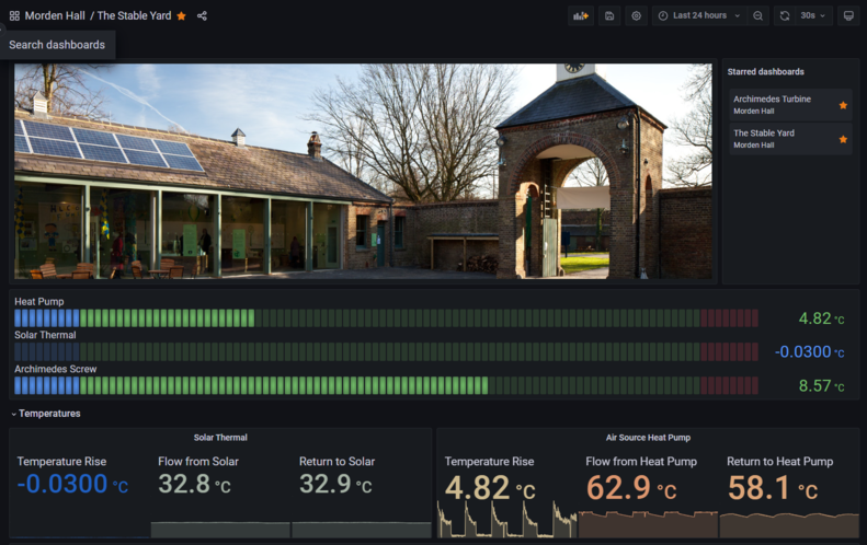
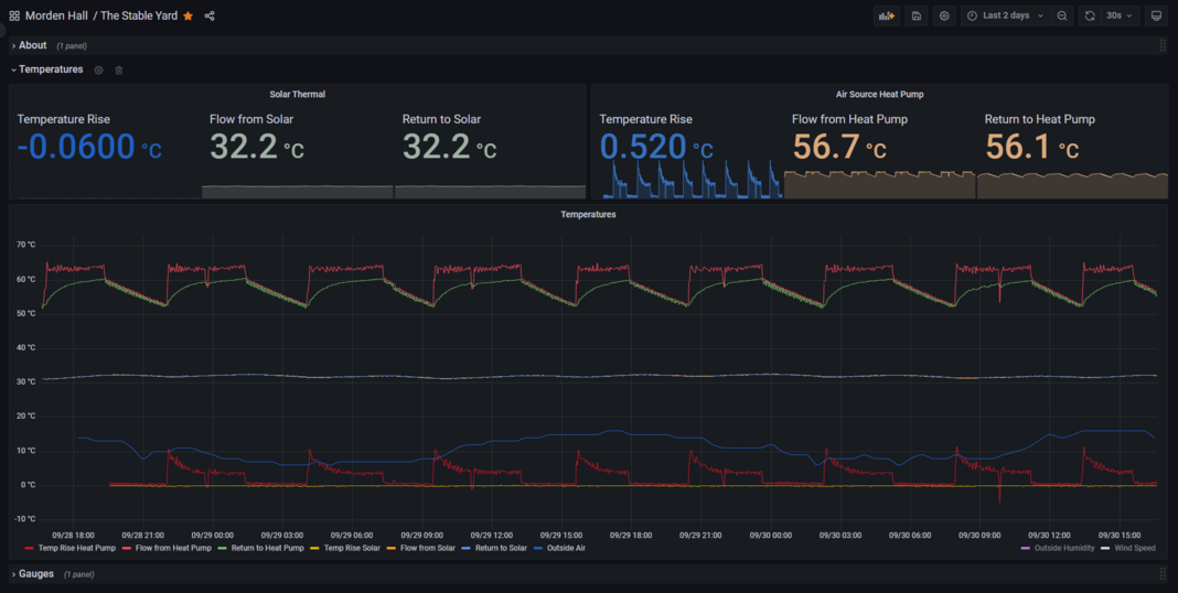
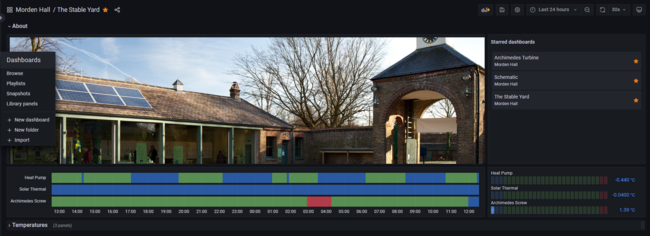
Now we have 2 days data from the solar thermal and the heat pump, we can see that the solar is kaput, while the heat pump is looking healthy, firing roughly 4 times per day, and is on most of the time delivering 63C heat (perfect peak temperature).

It does look like the heat pump circulating pump keeps going when the heat pump is off, causing the pipework around the plantroom to act as a radiator all the time. This can be easily confirmed and fixed.

Their looks like room to save carbon as follows:
* Control the heat pump circulating pump.
* Weather compensate the heat pump to reduce temperatures and achieve a more steady state operation to match actual loads.
* Get the solar thermal going. This is the only totally zero-carbon heat source and given the panel area should contribute a significant amount.
* Better room temperature control. I intend to fully examine the underfloor heating on next visit.
* Arguably, the biomass is also a further carbon saving - while marginal grid electricity generation is non-renewable - so bringing it back online would be of net planetary benefit. It is a make that is smokeless zone approved, however I have not looked at it yet so will follow up, possibly with a pressure test to determine if/where there is a leak.

The system controls are all mechanical and we may find room for further savings once we examine the hot water loops and the operation of the thermal store pumps. Any upgrades can be made using the new controller we fitted this week.

We will also be:
* Bringing the TV display back online. It would appear the original kit above the TV is dead so we can easily replace with a small controller and display the online dashboards. It has a slideshow feature so we can tailor screens to the display size and rotate them every minute or so.
* Adding a pressure sensor the the thermal stores. This will help determine the nature of the pressure loss you are experiencing. We can also add a simple email alarm to this.

As per request we are very happy to pull in operational data from the hydro-electric screw turbine. This will require another similar small panel in the shed, and will provide:
* Temperature readings from generator casing
* Meter readings of energy generated
* We can pull in a webcam feed of the turbine (if only for project demonstration)

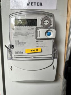
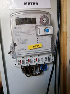
We will add these to the dashboard. I just need to confirm if the meter has either pulsed output, M-Bus or Modbus.  My photo came out blurry. Could yo send me another photo of the meter labelling, thanks.

Kind regards,
Richard.
System Pressures
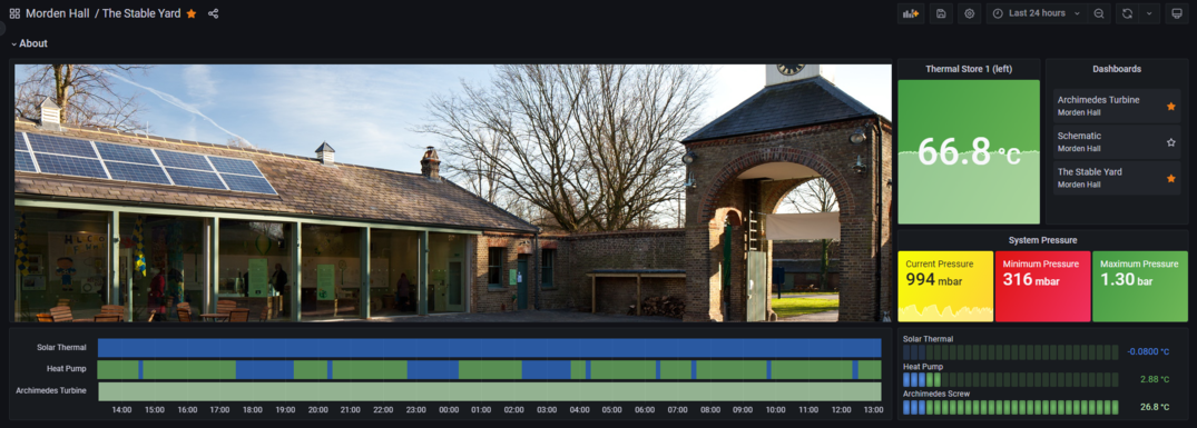
The system has been losing pressure regularly, causing hot water to fail, and as part of the monitoring we have added a pressure sensor to the main system to investigate.
A Grundfos RPS sensor was used, providing both static pressure and temperature signals. It was fitted near the top of Thermal Store 1.
As soon as data became available the reason became clear... the expansion vessel is not functioning, and pressures climb by around a bar during reheat cycles, then drop. On the first heat up following a top-up, water is discharged with nowhere else to go, and then when the store cools at all, pressure drop significantly.
We have added minimum and maximum pressures to the dashboard with a traffic light theme to draw attention to further problems.
As a matter of urgency the expansion vessel requires either a service or replacement.
The following graph shows heat pump output temperature in orange and system pressure in blue.
The ability to plot multiple historical metrics side by side is a great advantage in fault finding.
Monitoring Hydro-Electric Archimedes Turbine
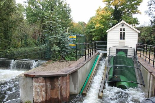
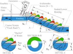
The Archimedes Turbine generates electricity from a relatively low water head of a few metres, making them ideal for smaller sites between 5kW and 500kW.
They are safer to the passage of fish than traditional hydroelectric, and resilient to the passage of large debris.
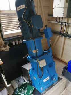
The turbine at Morden Hall is an 8.5kW system, capable of providing electricity for roughly 18 medium sized properties. At current electricity prices (2022) it has a roughly 10 year pay-back, if continuously operational.
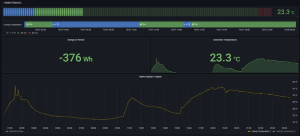
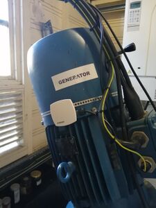
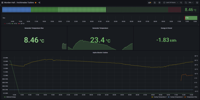
One of the clients requests is to add some visibility to the hydro-electric system. This is to include temperature monitoring of the turbine casing, and monitoring the electricity generated.
Principles of Operation https://onlinelibrary.wiley.com/doi/abs/10.1002/er.6893
Site Works 07/10/2022
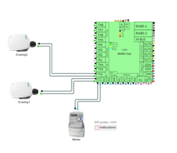
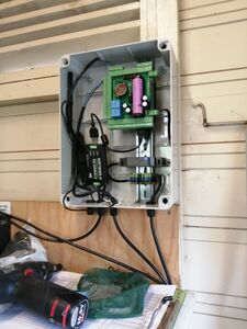
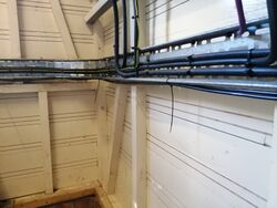
The purpose of the visit was to install the control panel, cabling, and get at least one sensor online.
Time taken: 45 minutes.
A follow up visit will be required to add additional sensors and wire in the pulsed output from the meter.
| Description | Quantity | Cost | Notes |
|---|---|---|---|
| Open Source Control Panel | 1 | ||
| NTC Pipe Temperature Sensors | 2 | ||
| 2 Core 0.75mm Silicone Cable | 14m |
Wiring Diagram heatweb_morden_hall_2.json
Dashboarding
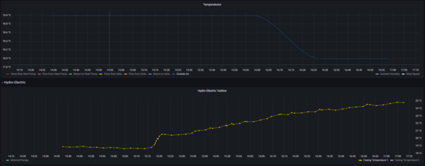
Following the visit, the data can be seen on the client dashboard.
First Fault (2nd night monitoring)
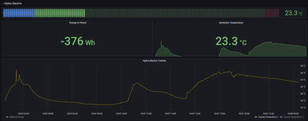
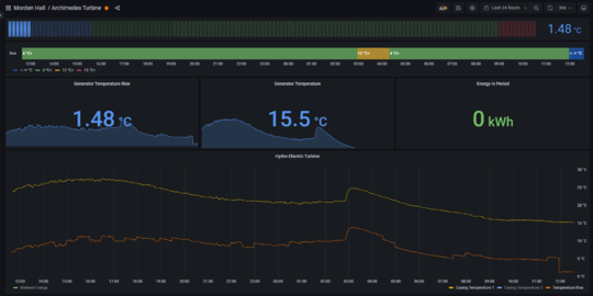
It wasn't long before the Archimedes turbine fell over. The events happened overnight, however we have data on the events that may help prevent future occurances.
