Difference between revisions of "Putney Plaza"
| (67 intermediate revisions by 2 users not shown) | |||
| Line 12: | Line 12: | ||
* [http://heatweb.co.uk/w/index.php?title=Putney_Plaza_Manual Existing Wiki (DPS/Thermal Integration)] | * [http://heatweb.co.uk/w/index.php?title=Putney_Plaza_Manual Existing Wiki (DPS/Thermal Integration)] | ||
* {{#l:Mechanical_Equipment_Schedule_-_Putney_Plaza_-_Construction_Issue_140707.pdf|Mechanical Equipment Schedule}} | * {{#l:Mechanical_Equipment_Schedule_-_Putney_Plaza_-_Construction_Issue_140707.pdf|Mechanical Equipment Schedule}} | ||
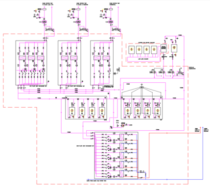
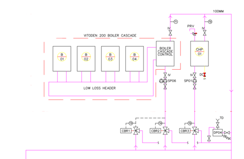
* {{#l:PplazaMS-001PlantroomSchematicC3.pdf|Plantroom Schematic}}<br>[[File:Ppschembr.png|frameless| | * {{#l:PplazaMS-001PlantroomSchematicC3.pdf|Plantroom Schematic}}<br>[[File:Ppschembr.png|frameless|429x429px]] | ||
== 2022 Plan == | |||
* Get internet to panel <code>Completed 26/09/22</code> | |||
* Confirm readings from 4 new boiler sensors <code>Completed 26/09/22</code> | |||
* Obtain remote access to new Internet Router | |||
*Install VPN | |||
*Add sensors to CHP (flow / return) | |||
* Install new MQTT services into cloud server using Docker (data send directly to server) <code>Completed 26/09/22</code> | |||
* Install Grafana and update cloud server dashboard and wiki with new data | |||
* Regain control over boiler valves from new panel. | |||
* Update controller in tank room for buffer/boiler control, and replace buffer sensors. This will provide renewed monitoring and control over the boiler circuits. | |||
* Update sensors in each buffer tank Rewire boiler demand switch | |||
* Fit a control panel on one of the roof tops, a well as a board inside the existing control panel. The new panel will be used to collect data and establish permanent requirements that will then be implemented via existing panel. We need to better understand what the existing panels wire to, then rewire sensors and outputs to the new controller to reinstate operation. | |||
* Once one heat pump is working and visible, the others can be addressed. | |||
* Reinstate heat meter when boilers ready for a workout | |||
* Fully commission boilers and valves | |||
* Update boiler pump to a Magna3D for variable speed control. | |||
== BMS Controls == | |||
{{Blockred| | |||
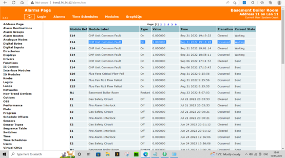
* No visibility on existing Trend controls. | |||
* No way to check or alter controls logic. | |||
* No separation in trunking between high and low voltage cables. | |||
}} | |||
{{Block|Plate heat exchangers are already fitted with open control system and are accessible over the network.}} | |||
<gallery widths="333" heights="444"> | |||
File:Cp02623.jpg|BMS Panel | |||
File:IMG 20220823 082155.jpg|Trunking | |||
File:W082428.jpg|Power and unshielded Ethernet | |||
</gallery> | |||
<gallery widths="555" heights="333"> | |||
File:Network1.PNG|Network scan shows up operation plate heat exchanger systems. Fing is a free tool that is very useful for scanning networks. See https://www.fing.com/ | |||
File:Pptrend.png|The existing Trend system can be accessed as a guest. | |||
</gallery> | |||
== Internet Connectivity == | |||
{{Blockred| | |||
The site has been plagued with internet connectivity problems resulting from changes in internet provider. This has resulted in long periods without access to controls or visibility. | |||
}} | |||
Key lessons learned from the experiences include: | |||
{{Block| | |||
* You only require standard simple internet, with no fancy management. A standard domestic connection is perfect. | |||
* Routers should have the standard functions including: | |||
** Remote access via either http or https | |||
** The ability to setup port forwarding | |||
* A fixed IP address is preferred. Dynamic DNS services can be used instead, however there may be occasional loss of connections as IP addresses update when they change. | |||
* With engineer rates in the £100s per day, changing an internet setup to save a few pounds is a false economy that requires an engineer to attend site and reinstate port forwarding rules etc. | |||
* Routers should be safe from tampering and accidental damage. A locked BMS cabinet is the preferred position. | |||
* Where internet is not already available as per preceding points, a GSM modem should be included in the initial fit. It is common for phone lines and internet providers to take weeks if not months to get everything in place. Connectivity should be available from the first day on site. | |||
}} | |||
<br> | |||
== Air Source Heat Pumps == | == Air Source Heat Pumps == | ||
An initial survey of the roof top heat pump systems has highlighted some significant problems. | An initial survey of the roof top heat pump systems has highlighted some significant problems. | ||
{{Blockred |Problems with visibility: | |||
* No way to understand current operation, without any feed into a monitoring (SCADA) system. | * No way to understand current operation, without any feed into a monitoring (SCADA) system. | ||
* No alarming | * No alarming | ||
* No performance monitoring | * No performance monitoring}} | ||
{{Blockred |At least one of the main circulating pumps to the heat pumps control has never been wired up, fault should have been caught by a number of methods, from a lack of pump DP feeding into an alarm, a lack of temperatures, or from heat pump heat meters never showing any energy, however a fundamental lack of visibility has let this go unnoticed until now. it is believed that these pumps haven’t worked since installation.}} | |||
<br> | <br> | ||
| Line 26: | Line 88: | ||
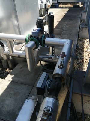
File:Pp4.jpg|Roof top heat pumps | File:Pp4.jpg|Roof top heat pumps | ||
File:Pp5.jpg|Roof top heat pumps | File:Pp5.jpg|Roof top heat pumps | ||
File:Pp6.jpg|Unwired circulating pump to heat pump | File:Pp6.jpg|Unwired control of circulating pump to heat pump. | ||
File:Pp7.jpg|Heat pump control panel | File:Pp7.jpg|Heat pump control panel | ||
</gallery> | </gallery> | ||
| Line 37: | Line 99: | ||
# Monitor performance and setup alarm routes | # Monitor performance and setup alarm routes | ||
== | [[Category:Projects]] | ||
==Extract Air Ventilation System== | |||
Properties are fitted with an air extraction system that pumps air from properties to the roof. | |||
{{Blockred |Problems discovered (by residents): | |||
* Air extract is running at full speed, pumping heated air from properties to outside. | |||
* Without heat pumps working, none of this heat is recovered. | |||
* Cracks in the fabric of properties allows cold fresh air in.}} | |||
[ | DIY solution. | ||
{{Block| | |||
Under guidance, residents have been able to temporarily turn off the extraction fans, with an immediate effect on building temperatures. [Dec 2022]}} | |||
==Boilers== | ==Boilers== | ||
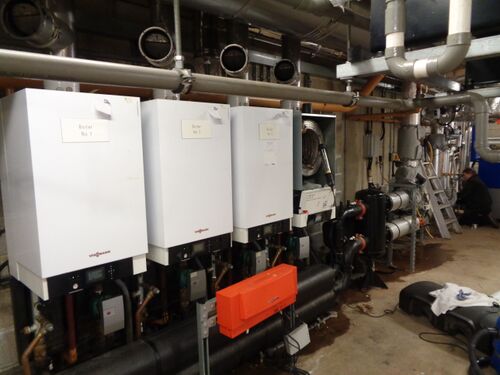
[[File:Vitogate 300.pdf|none|thumb|194x194px|Vitogate 300 Modbus Gateway]] | |||
=== Hydraulic Arrangement === | === Hydraulic Arrangement === | ||
| Line 81: | Line 127: | ||
<br> | <br> | ||
| Line 89: | Line 132: | ||
=== Correct Function === | === Correct Function === | ||
{{Block| | |||
* Boilers should be sequenced from buffer stores. As each of the four series buffers deplete in temperature, an additional boiler should fire up. | * Boilers should be sequenced from buffer stores. As each of the four series buffers deplete in temperature, an additional boiler should fire up. | ||
* Lead boilers should be rotated. | * Lead boilers should be rotated. | ||
| Line 94: | Line 138: | ||
* Loading valves are fitted to the back end of the boilers. These are modulated to maintain a minimum temperature into the header from the system, preventing water colder than 55C from entering the boilers, however the use of a header makes the valves potentially redundant. [They are currently uncontrolled] | * Loading valves are fitted to the back end of the boilers. These are modulated to maintain a minimum temperature into the header from the system, preventing water colder than 55C from entering the boilers, however the use of a header makes the valves potentially redundant. [They are currently uncontrolled] | ||
* The shunt pump between the header and the buffer storage must be controlled to remove the heat from all firing boilers, maintaining flow temperatures across the header, with a varying number of boilers firing and fluctuations in return temperature. As such it needs to modulate depending on the temperatures across the header. | * The shunt pump between the header and the buffer storage must be controlled to remove the heat from all firing boilers, maintaining flow temperatures across the header, with a varying number of boilers firing and fluctuations in return temperature. As such it needs to modulate depending on the temperatures across the header. | ||
}} | |||
=== Measuring Boiler Outputs === | === Measuring Boiler Outputs === | ||
| Line 118: | Line 163: | ||
<iframe key="wiki" align="right" width="100%" height=" | <iframe key="wiki" align="right" width="100%" height="850" level="" path="/gojs/samples/wiring23.html?cid=heatweb_putney_heat_meter_1.json&palette=heatweb_sensors.json&height=700px" /> | ||
<pre class="wikidiagrams"> | <pre class="wikidiagrams"> | ||
heatweb_zcccaef4ahl.json Boiler Controller | |||
heatweb_putney_heat_meter_1.json Heat Meter | heatweb_putney_heat_meter_1.json Heat Meter | ||
heatweb_wiring_boilers_4.json Boilers x4 | |||
heatweb_wiring_grundfos_pumps.json Grundfos | |||
heatweb_sensor_locations_jan2023.json Locations Jan 2023 | |||
</pre> | </pre> | ||
https://hwwiki.ddns.net/ui/wiring/wiring22/QmUHopoYv7NE5QUYppfTxaaLoRni4QjjNkAPpkXadFhmvf | |||
=== Initial Findings === | === Initial Findings === | ||
{{Blockred| Elevated Return temperatures from the system.}} | |||
<br> | |||
As part of the upgrades we are moving the client interface into Grafana. The image below shows the initial dashboard created to show the boiler temperatures. | As part of the upgrades we are moving the client interface into Grafana. The image below shows the initial dashboard created to show the boiler temperatures. | ||
| Line 141: | Line 194: | ||
'''''https://hw16.ddns.net/dashboard/snapshot/fAqR4khHc24jSY6TKq1ZqMbEeRvrVFYg?orgId=1&refresh=30s''''' | '''''https://hw16.ddns.net/dashboard/snapshot/fAqR4khHc24jSY6TKq1ZqMbEeRvrVFYg?orgId=1&refresh=30s''''' | ||
== Header Control == | |||
{{Blockred| | |||
The current fixed speed shunt pump between the header and the storage tanks is not compatible with boiler sequencing, where the output varies with the number of boilers firing and the shunt pump needs to vary to match output. | |||
}} | |||
<br> | |||
The following graphs shows 1 week of operation. On 31st at 10:30 the boiler outputs can be seen to change in profile to a steady 80C flow temperature. This is as a result of ongoing boiler works, and is believed to result from a change in pump speed, reducing the flow rate through the boiler so it is able to achieve target temperature of 80C. | The following graphs shows 1 week of operation. On 31st at 10:30 the boiler outputs can be seen to change in profile to a steady 80C flow temperature. This is as a result of ongoing boiler works, and is believed to result from a change in pump speed, reducing the flow rate through the boiler so it is able to achieve target temperature of 80C. | ||
| Line 167: | Line 225: | ||
[[File:Putneyboilersweek1a.png|frameless|942x942px]] | [[File:Putneyboilersweek1a.png|frameless|942x942px]] | ||
The following dashboard shows the problem with current header control. | |||
{{Blockred| | |||
Even though boilers are capable of 80C, we are experiencing system flow temperatures of only 60C. | |||
It appears the pump on boiler 4 may be running and mixing cold into the flow. | |||
}} | |||
[[File:Ppheaderissue1.png|frameless|942x942px]] | |||
https://hw16.ddns.net/dashboard/snapshot/rtQ6DgXmhlkFwbI42HLTSTyo8UaLRkfV | |||
== CHP == | == CHP == | ||
[[File:DSC00011.jpg|thumb|CHP Heat Exchanger and Pumps]] | [[File:DSC00011.jpg|thumb|CHP Heat Exchanger and Pumps]] | ||
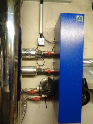
{{Blockred | The CHP is piped up differently to the schematic. The schematic shows the CHP outlet combining with the boiler output. In reality, the CHP feeds into system return to the header acting as a preheat to the boilers. The existing pipework arrangement can be made to work, although it will not be as efficient as the original design, with elevated boiler return temperatures.}} | |||
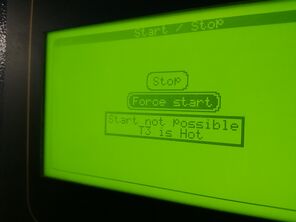
{{Blockred | The CHP is offline. }} | |||
<br><gallery widths="333" heights="222"> | |||
File:IMG 20220823 091616.jpg|Full Stop | |||
File:Chp091602.jpg|Pressure Alarm | |||
File:Chp091857.jpg|Inlet Too Hot | |||
</gallery> | |||
Temperature sensors have been added to individual boilers as well as the CHP, so we have clear indications on all plantroom heat sources. | Temperature sensors have been added to individual boilers as well as the CHP, so we have clear indications on all plantroom heat sources. | ||
| Line 177: | Line 257: | ||
* ''tCHPR'' is the CHP engine return | * ''tCHPR'' is the CHP engine return | ||
Note that the red and yellow (flow and return) were labelled incorrectly, hence the swap in values when corrected. | Note that the red and yellow (flow and return) were labelled incorrectly, hence the swap in values when corrected. | ||
[[File:Putneyboilerschp.png|frameless|984x984px]] | |||
[[File: | === CHP Online === | ||
{{Block | On 15th November the CHP is brought back online. }} | |||
https://hw16.ddns.net/dashboard/snapshot/xHUrXx5TAFhelyjJFC02KS2yzOYlqmY6 (2h) | |||
https://hw16.ddns.net/dashboard/snapshot/ayqMLUCxLI9jhC9M69SsidbMEpvqrxuS (2d) | |||
[[File:Chpon.png|frameless|988x988px]] | |||
== Plate Heat Exchanger Sets == | |||
{{Blockred|Problems Include: | |||
* Lack of visibility since internet service provider was changed. | |||
* Historical problems with water quality. Most components have been replaced, however there may be issues with a few sets still. | |||
* Positioning of control boxes on the front of the heat exchanger sets has been a problem with water ingress from leaks above. | |||
* Pumps have been upgraded to Magna3 with Modbus, but require upgrading of controls to provide variable speed control.}} | |||
<br> | |||
[[File:Pphxsets.jpg|frameless|704x704px]]{{Block | On 19th November a reverse proxy was installed to provide remote access to heat exchanger sets. This has brought data online for most sets, which has been linked to a Grafana dashboard.}}The initial data has highlighted a few problems that need investigating. | |||
{{Blockred|Problems: | |||
* Lack of visibility on 3 systems | |||
* Only one of the two radiator exchangers is visible, and that one is running below setpoint.}} | |||
Version 1: | |||
[[File:Ppphex1.png|frameless|973x973px]] | |||
Version 2: | |||
[[File:Ppphex2.png|frameless|974x974px]] | |||
== Client Dashboards == | == Client Dashboards == | ||
The latest Grafana user interface can be found at... https://hw16.ddns.net/ | The dashboarding is migrating from the current Google VM to a hosted Grafana stack. | ||
This is primarily to cut out the need for cloud infrastructure, with Grafana providing storage, visualisation, reporting and alarming. | |||
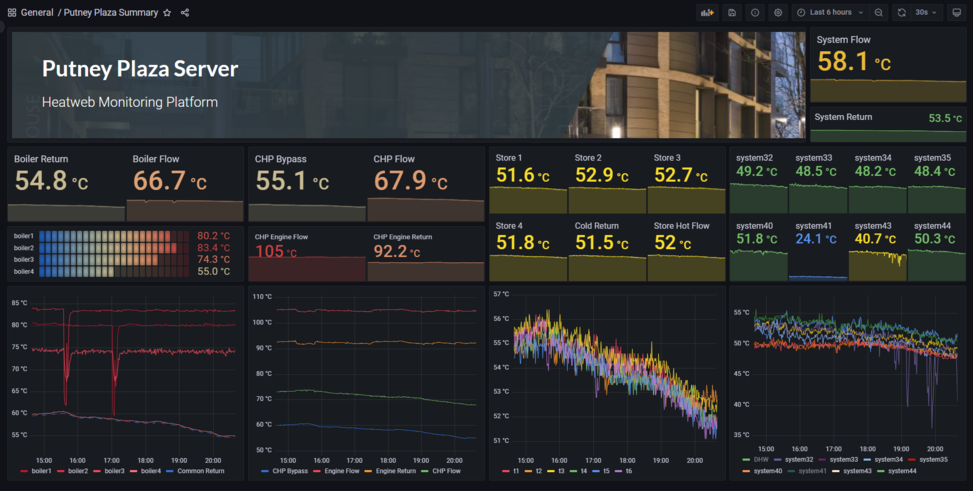
[[File:Ppdashf1.png|frameless|973x973px]] | |||
This latest dashboard now shows all available data, including boilers, CHP, buffer storage and heat exchanger sets. | |||
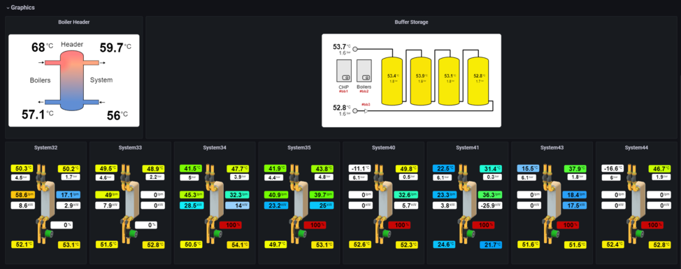
It also shows the existing graphics for the system, linked and coloured to data. | |||
[[File:Ppdashf3.png|frameless|974x974px]] | |||
The open Grafana user interface can be found at... https://hw16.ddns.net/ | |||
Login using '''''putney-plaza''''' for both username and password. (Note this may change without notice, but for now is open) | Login using '''''putney-plaza''''' for both username and password. (Note this may change without notice, but for now is open) | ||
== Reporting == | |||
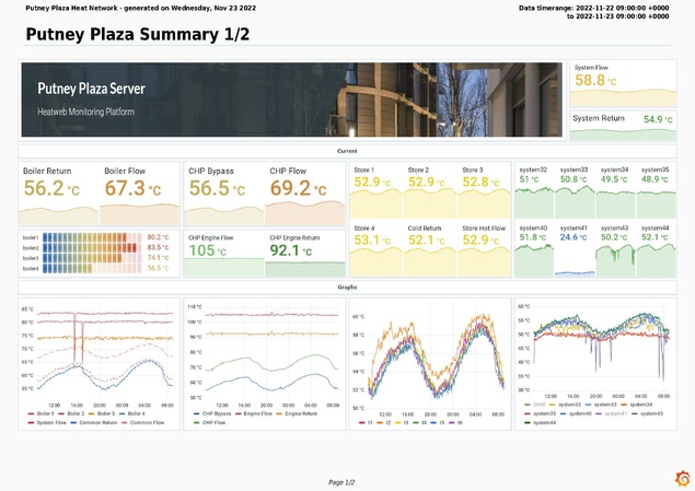
The following PDF report is scheduled to go out by email every morning at 09:00 (at the tail end of morning peak load), to the client, engineers and (technical) residents. | |||
[[File:Putney Plaza Heat Network-2022-11-23.pdf|none|thumb|635x635px|PDF Report]] | |||
Latest revision as of 09:11, 28 February 2023
To Do
- Investigate current state of heat pumps and CHP
- Install heat meters and controls
- Confirm current operation
- Recommission
- Remote dashboards
Existing Documentation
2022 Plan
- Get internet to panel
Completed 26/09/22 - Confirm readings from 4 new boiler sensors
Completed 26/09/22 - Obtain remote access to new Internet Router
- Install VPN
- Add sensors to CHP (flow / return)
- Install new MQTT services into cloud server using Docker (data send directly to server)
Completed 26/09/22 - Install Grafana and update cloud server dashboard and wiki with new data
- Regain control over boiler valves from new panel.
- Update controller in tank room for buffer/boiler control, and replace buffer sensors. This will provide renewed monitoring and control over the boiler circuits.
- Update sensors in each buffer tank Rewire boiler demand switch
- Fit a control panel on one of the roof tops, a well as a board inside the existing control panel. The new panel will be used to collect data and establish permanent requirements that will then be implemented via existing panel. We need to better understand what the existing panels wire to, then rewire sensors and outputs to the new controller to reinstate operation.
- Once one heat pump is working and visible, the others can be addressed.
- Reinstate heat meter when boilers ready for a workout
- Fully commission boilers and valves
- Update boiler pump to a Magna3D for variable speed control.
BMS Controls
- No visibility on existing Trend controls.
- No way to check or alter controls logic.
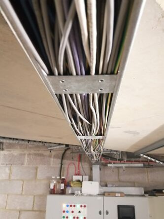
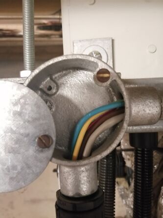
- No separation in trunking between high and low voltage cables.
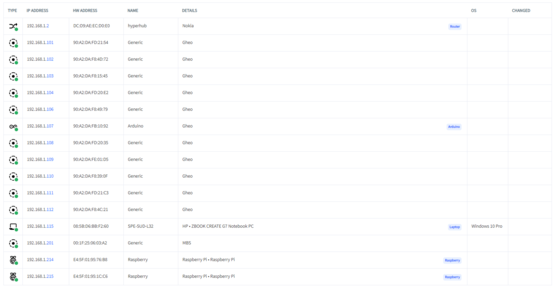
Network scan shows up operation plate heat exchanger systems. Fing is a free tool that is very useful for scanning networks. See https://www.fing.com/
Internet Connectivity
The site has been plagued with internet connectivity problems resulting from changes in internet provider. This has resulted in long periods without access to controls or visibility.
Key lessons learned from the experiences include:
- You only require standard simple internet, with no fancy management. A standard domestic connection is perfect.
- Routers should have the standard functions including:
- Remote access via either http or https
- The ability to setup port forwarding
- A fixed IP address is preferred. Dynamic DNS services can be used instead, however there may be occasional loss of connections as IP addresses update when they change.
- With engineer rates in the £100s per day, changing an internet setup to save a few pounds is a false economy that requires an engineer to attend site and reinstate port forwarding rules etc.
- Routers should be safe from tampering and accidental damage. A locked BMS cabinet is the preferred position.
- Where internet is not already available as per preceding points, a GSM modem should be included in the initial fit. It is common for phone lines and internet providers to take weeks if not months to get everything in place. Connectivity should be available from the first day on site.
Air Source Heat Pumps
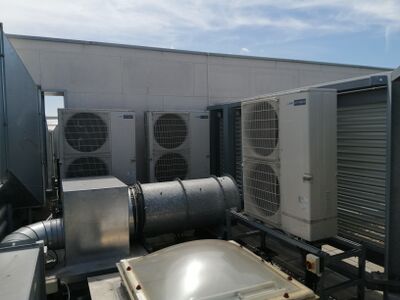
An initial survey of the roof top heat pump systems has highlighted some significant problems.
- No way to understand current operation, without any feed into a monitoring (SCADA) system.
- No alarming
- No performance monitoring
Next Steps
- Obtain all relevant manufacturers instructions on heat pumps and fitted controls
- Upgrade controls with open control system and remote monitoring so that the heat pumps can be setup and controlled as required
- Recommission heat pumps using new system
- Monitor performance and setup alarm routes
Extract Air Ventilation System
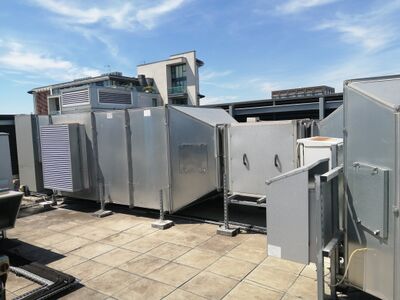
Properties are fitted with an air extraction system that pumps air from properties to the roof.
- Air extract is running at full speed, pumping heated air from properties to outside.
- Without heat pumps working, none of this heat is recovered.
- Cracks in the fabric of properties allows cold fresh air in.
DIY solution.
Boilers
Hydraulic Arrangement
Correct Function
- Boilers should be sequenced from buffer stores. As each of the four series buffers deplete in temperature, an additional boiler should fire up.
- Lead boilers should be rotated.
- The flow rate through the boilers is controlled (via pump speed) by the boiler (or is manually set) and cannot be externally controlled. The flow rate will allow for a maximum temperature drop across the boiler, of 20C.
- Loading valves are fitted to the back end of the boilers. These are modulated to maintain a minimum temperature into the header from the system, preventing water colder than 55C from entering the boilers, however the use of a header makes the valves potentially redundant. [They are currently uncontrolled]
- The shunt pump between the header and the buffer storage must be controlled to remove the heat from all firing boilers, maintaining flow temperatures across the header, with a varying number of boilers firing and fluctuations in return temperature. As such it needs to modulate depending on the temperatures across the header.
Measuring Boiler Outputs
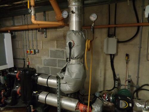
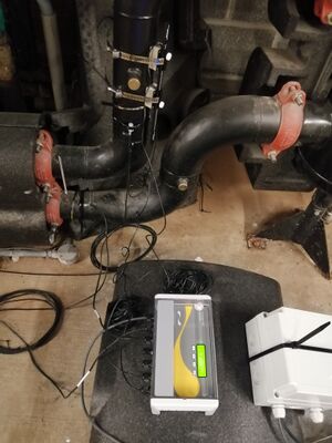
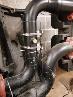
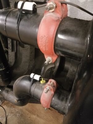
A Micronics Clamp-On Heat Meter has been temporarily installed onto boilers in order to confirm the peak outputs of each boiler.
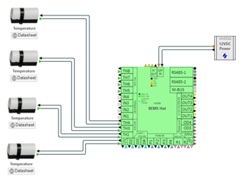
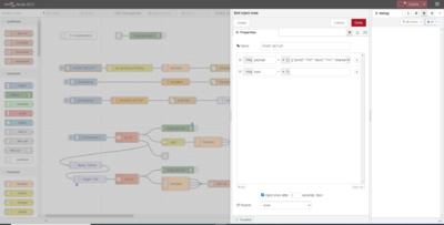
Wiring New NTC Sensors
heatweb_zcccaef4ahl.json Boiler Controller
heatweb_putney_heat_meter_1.json Heat Meter
heatweb_wiring_boilers_4.json Boilers x4
heatweb_wiring_grundfos_pumps.json Grundfos
heatweb_sensor_locations_jan2023.json Locations Jan 2023
https://hwwiki.ddns.net/ui/wiring/wiring22/QmUHopoYv7NE5QUYppfTxaaLoRni4QjjNkAPpkXadFhmvf
Initial Findings
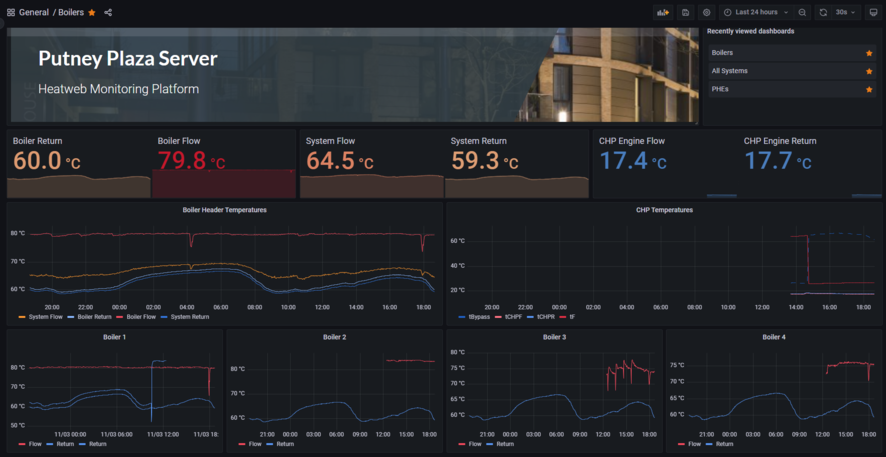
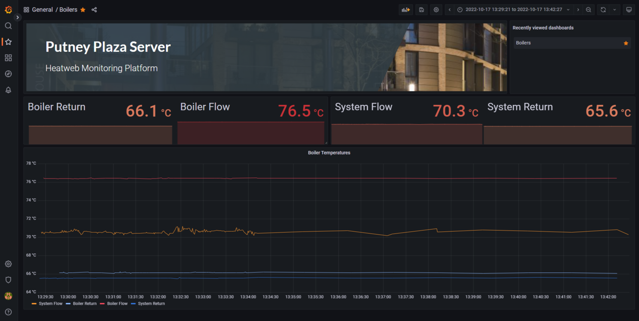
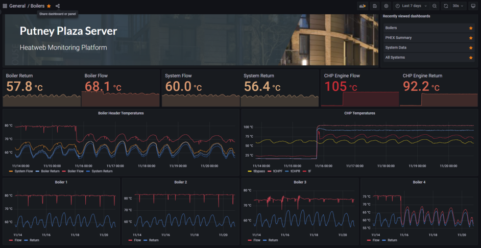
As part of the upgrades we are moving the client interface into Grafana. The image below shows the initial dashboard created to show the boiler temperatures.
Viewing the data highlights a few things...
- We have data resolution higher than needed, with every reading coming through, almost every second. This uses up more SIM data than needed, and results in graphs taking longer to load, with a vast number of data points to load if looking at a few days data. To correct this we placed a "Report By Exception" rule, whereby data is only sent every minute, or if it changes by more than 0.5C since the last send. This way, when there is little movement in temperatures we get a data point every minute, but when temperatures change rapidly, we get higher resolution (down to every second) so we don't miss anything interesting. The difference can be seen in the graph, looking at the orange System Flow reading, where the change results in less data points.
- The System Flow temperature is nearer the return than the blow from the boilers. This means that the system flow rates are roughly double the boiler flow rates. This causes unnecessary mixing and we lose the higher boiler temperatures. It is clear that the method of controlling pump speed needs examining, potentially introducing pump speed control and tying it in with boiler sequencing.
- The system return temperature is roughly 65C, which is too high.
https://hw16.ddns.net/dashboard/snapshot/fAqR4khHc24jSY6TKq1ZqMbEeRvrVFYg?orgId=1&refresh=30s
Header Control
The current fixed speed shunt pump between the header and the storage tanks is not compatible with boiler sequencing, where the output varies with the number of boilers firing and the shunt pump needs to vary to match output.
The following graphs shows 1 week of operation. On 31st at 10:30 the boiler outputs can be seen to change in profile to a steady 80C flow temperature. This is as a result of ongoing boiler works, and is believed to result from a change in pump speed, reducing the flow rate through the boiler so it is able to achieve target temperature of 80C.
https://hw16.ddns.net/dashboard/snapshot/SSo8vPROq9xZmOLr7cr0t8pSObu5Jiyc
What this clearly shows is that the boilers are generating 80C heat, but the system rarely sees 70C, because the flow rates are much higher on the system side. This indicates that the system side pump needs better control, so that flow rates are better matched to boilers, and the boiler flow temperatures reach thermal stores. As the pump is slowed down, the system flow temperature will increase. Once it has dropped to match the boilers, the 80C to the system (orange) will be very close to the boiler supply (red).
If pump flow rates are dropped too far, then not all the heat generated will be removed and boilers will modulate down and start cycling significantly. This is why a fixed speed approach can never work.
To implement a simple control logic we would vary system side flow rates to achieve an equal temperature difference between the hot pipes as the cold pipes.
E.g. Boiler output is 80C, System flow is 77C (a 3C difference), so if System return is 60C, we control pump to achieve 63C on the return to the boilers (speed up to reduce return temp diff).
This maintains matched flow rates on the system side, and ensures boilers remain at full output until stores are satisfied. With the current fixed settings this has never been possible. At startup, when boilers may be sluggish to heat up, the system pump will be at a minimum speed (or off), only speeding up as boiler temperatures climb above 75C. This will prevent cold plugs making their way to heat exchangers.
Zooming in on one of the points of cycling (below), one can see the boiler turning off [17:53:20], followed by the pump off [17:54:00], followed by restart [17:57:15].
The entire cycle lasts approximately 10 minutes, repeating roughly every 10 hours when return temperatures are at their highest.
The following dashboard shows the problem with current header control.
Even though boilers are capable of 80C, we are experiencing system flow temperatures of only 60C. It appears the pump on boiler 4 may be running and mixing cold into the flow.
https://hw16.ddns.net/dashboard/snapshot/rtQ6DgXmhlkFwbI42HLTSTyo8UaLRkfV
CHP
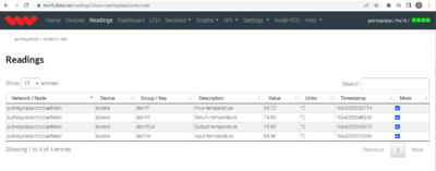
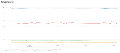
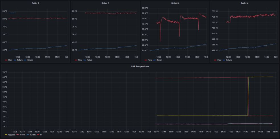
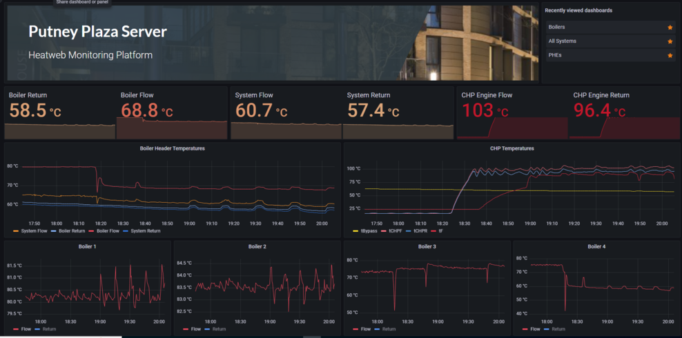
Temperature sensors have been added to individual boilers as well as the CHP, so we have clear indications on all plantroom heat sources.
- tBypass is the temperature on the section of boiler return the CHP is fitted across. This is the temperature of water fed to the CHP.
- tF is the temperature out of the CHP on the system, feeding into the boiler return.
- tCHPF is the CHP engine flow (coming directly out of the CHP before heat exchanger)
- tCHPR is the CHP engine return
Note that the red and yellow (flow and return) were labelled incorrectly, hence the swap in values when corrected.
CHP Online
https://hw16.ddns.net/dashboard/snapshot/xHUrXx5TAFhelyjJFC02KS2yzOYlqmY6 (2h)
https://hw16.ddns.net/dashboard/snapshot/ayqMLUCxLI9jhC9M69SsidbMEpvqrxuS (2d)
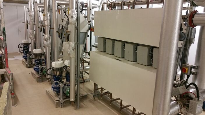
Plate Heat Exchanger Sets
- Lack of visibility since internet service provider was changed.
- Historical problems with water quality. Most components have been replaced, however there may be issues with a few sets still.
- Positioning of control boxes on the front of the heat exchanger sets has been a problem with water ingress from leaks above.
- Pumps have been upgraded to Magna3 with Modbus, but require upgrading of controls to provide variable speed control.
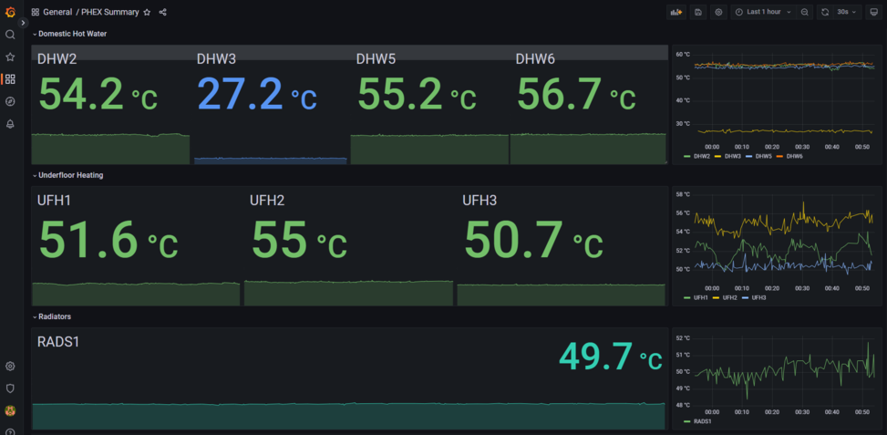
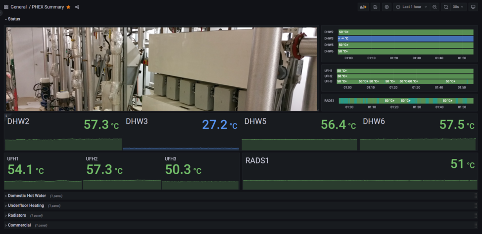
The initial data has highlighted a few problems that need investigating.
- Lack of visibility on 3 systems
- Only one of the two radiator exchangers is visible, and that one is running below setpoint.
Version 1:
Version 2:
Client Dashboards
The dashboarding is migrating from the current Google VM to a hosted Grafana stack.
This is primarily to cut out the need for cloud infrastructure, with Grafana providing storage, visualisation, reporting and alarming.
This latest dashboard now shows all available data, including boilers, CHP, buffer storage and heat exchanger sets.
It also shows the existing graphics for the system, linked and coloured to data.
The open Grafana user interface can be found at... https://hw16.ddns.net/
Login using putney-plaza for both username and password. (Note this may change without notice, but for now is open)
Reporting
The following PDF report is scheduled to go out by email every morning at 09:00 (at the tail end of morning peak load), to the client, engineers and (technical) residents.
