Difference between revisions of "Solar Heat Energy Demonstrator"
| (33 intermediate revisions by 2 users not shown) | |||
| Line 25: | Line 25: | ||
== Documents == | == Documents == | ||
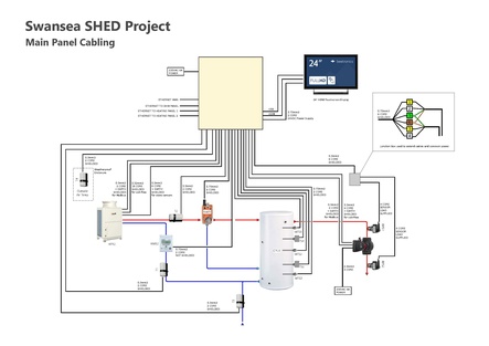
[[File:Shed_controls_1.pdf|border|443x443px]] | |||
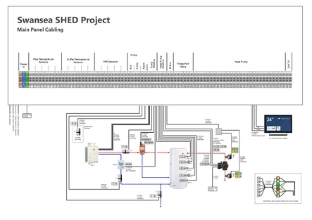
[[File:Shed_controls_2.pdf|border|443x443px]] | |||
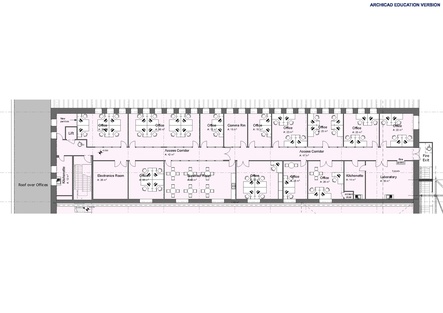
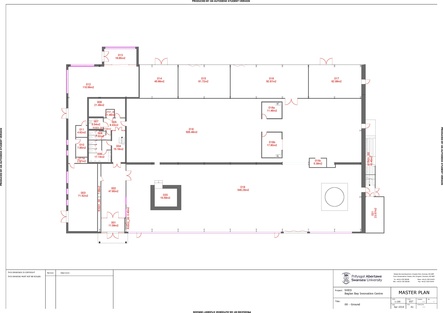
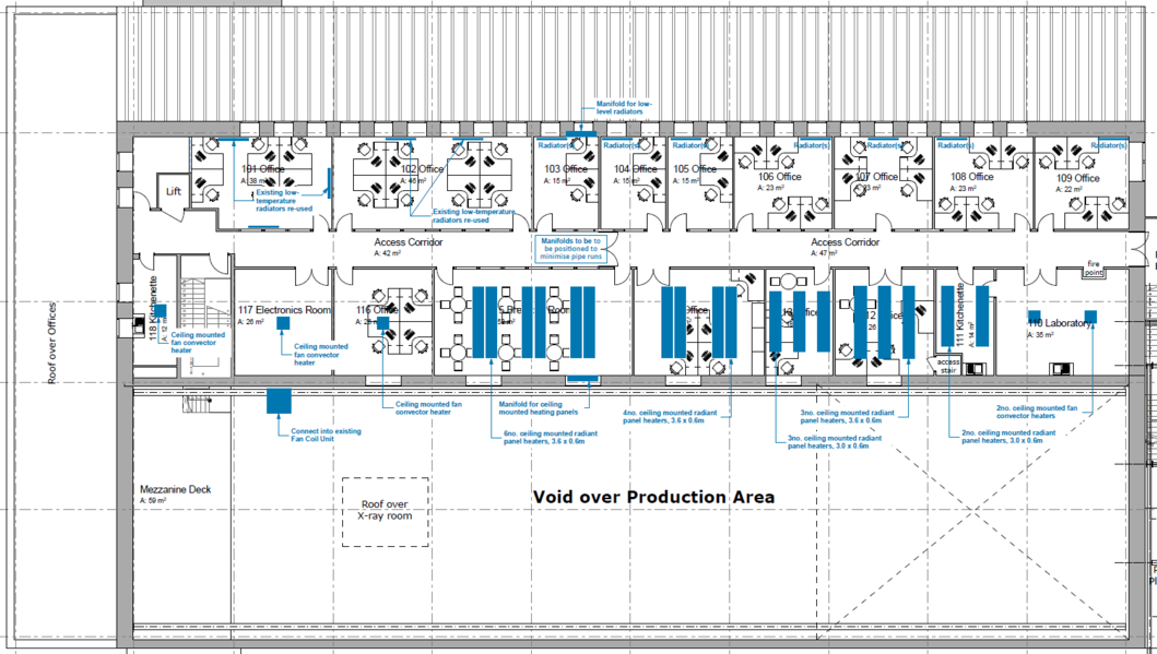
[[File:Proposed_SHED_Upgrading_Works_-_first_floor_layout.pdf|border|443x443px]] | [[File:Proposed_SHED_Upgrading_Works_-_first_floor_layout.pdf|border|443x443px]] | ||
| Line 51: | Line 55: | ||
== System Drawings == | == System Drawings == | ||
<iframe key="wiki" align="right" width="100%" height="1150" level="" path="/gojs/samples/ | <iframe key="wiki" align="right" width="100%" height="1150" level="" path="/gojs/samples/wiring24.html?cid=heatweb_shed_schematic_2.json&palette=heatweb_sensors.json&height=800px" /> | ||
<pre class="wikidiagrams"> | <pre class="wikidiagrams"> | ||
heatweb_shed_schematic_2e.json Latest Schematic + Electric | |||
heatweb_wiring_shed_heating_stack.json Heating A | |||
heatweb_wiring_shed_heating_a1.json Heating A1 | |||
heatweb_wiring_shed_heating_a2.json Heating A2 | |||
heatweb_wiring_shed_heating_a3.json Heating A3 | |||
heatweb_wiring_shed_heating_a4.json Heating A4 | |||
heatweb_shed_wiring_heat_in.json Wiring Heat Input Panel | heatweb_shed_wiring_heat_in.json Wiring Heat Input Panel | ||
heatweb_shed_wiring_heat_pump.json Wiring Heat Pump | heatweb_shed_wiring_heat_pump.json Wiring Heat Pump | ||
heatweb_shed_wiring_dhw.json Wiring | heatweb_shed_dhw.json DHW Assembly | ||
heatweb_shed_wiring_dhw.json DHW Wiring | |||
heatweb_shed_wiring_coms.json Wiring Comms | |||
</pre> | </pre> | ||
| Line 107: | Line 117: | ||
{{#l:QAHV-N560YA-HPB_Service_Manual.pdf}}<br> | {{#l:QAHV-N560YA-HPB_Service_Manual.pdf}}<br> | ||
{{#l:QAHV-N560YA-HPB_Install_Manual.pdf}}<br> | {{#l:QAHV-N560YA-HPB_Install_Manual.pdf}}<br> | ||
{{#l:QAHV-N560YA-HPB-PI-SHEET.pdf}} | {{#l:QAHV-N560YA-HPB-PI-SHEET.pdf}}<br> | ||
{{#l:MELCOBEMS_MINI-PI-Sheet.pdf}}<br> | |||
{{#l:MELCOBEMS_MINI_A1M_ATW_Modbus_Register_Tables.pdf}} | |||
=== Technical Specifications === | === Technical Specifications === | ||
| Line 113: | Line 127: | ||
=== [[File:Qavh1.png|frameless|1065x1065px]] === | === [[File:Qavh1.png|frameless|1065x1065px]] === | ||
== | == Electric Boiler == | ||
https://viessmanndirect.co.uk/Catalogue/Viessmann-Electrical/Vitotron-Constant-Temp-Boiler/Vitotron-Electric-boiler-constant-temp-8-24-kW-Z020842 | |||
[[File: | [[File:Elecboiler.png]] | ||
== Domestic Hot Water == | |||
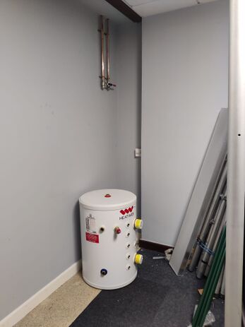
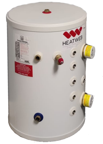
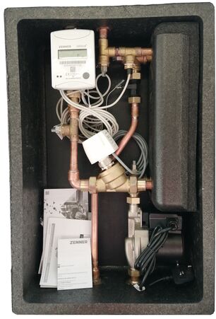
Hot water to be provided using a Storage HIU from Thermal Integration in partnership with a 90 litre unvented cylinder. | |||
=== Installation === | |||
[[File:Shed dhwcyl.png|frameless]] [[File:Shed-c.jpg|frameless|463x463px]] [[File:Shed dhwcyl2a.png|frameless|465x465px]][[File:Shed2023020321651.jpg|frameless|451x451px]] | |||
== Central Heating == | == Central Heating == | ||
| Line 194: | Line 198: | ||
The heat pump envelope allows loads to be increased 40% over these values if ever needed. | The heat pump envelope allows loads to be increased 40% over these values if ever needed. | ||
[[Radiator Charts]] | |||
=== Convector Outputs === | === Convector Outputs === | ||
| Line 1,766: | Line 217: | ||
10mm pipework, with a velocity of 0.042 litres/second provides 1.95 kW at an 11C drop. | 10mm pipework, with a velocity of 0.042 litres/second provides 1.95 kW at an 11C drop. | ||
We are running radiators at roughly 33C drop, three times this, so 10mm pipe can achieve a heating load of 6kW. | We are running radiators at roughly 33C drop, three times this, so 10mm pipe can achieve a heating load of 6kW through 10mm pipe. | ||
At peak peak, with heat pump running up to 90C, and return at 35C, it should be possible to achieve just over 9kW. | At peak peak, with heat pump running up to 90C, and return at 35C, it should be possible to achieve just over 9kW. | ||
[[File: | The following spreadsheet calculates pressure drops along central heating return pipes, for each zone. | ||
7 of the zones require a 15mm return pipe. The remainder can be in 10mm. | |||
Flow pipes are only ever in 10mm for 3m or less, when connecting to a heat emitter, until they join the main flow pipe, which is in 15, 22 and 28mm depending on number of zones the pipe feeds. | |||
[[File:Pipecalcsshed3.png|frameless|1191x1191px]] | |||
== Pump Selection == | == Pump Selection == | ||
| Line 1,789: | Line 246: | ||
!Quantity | !Quantity | ||
!Notes | !Notes | ||
!Supplied | |||
!Invoiced | |||
|- | |- | ||
|CO2 Air Source Heat Pump & Accessories | |CO2 Air Source Heat Pump & Accessories | ||
|1 | |1 | ||
| | |||
| | |||
| | | | ||
|- | |- | ||
| Line 1,797: | Line 258: | ||
|1 | |1 | ||
| | | | ||
|15/12/22 | |||
|6094 | |||
|- | |- | ||
| | |90 litre Direct Unvented Cylinder | ||
|1 | |1 | ||
| | | | ||
|18/1/23 | |||
|6095 | |||
|- | |- | ||
|Plate Heat Exchanger Recovery Unit (inc pump) | |Plate Heat Exchanger Recovery Unit (inc pump) | ||
|1 | |1 | ||
| | |||
| | |||
| | | | ||
|- | |- | ||
| Line 1,809: | Line 276: | ||
|1 | |1 | ||
| | | | ||
|15/12/22 | |||
|6094 | |||
|- | |- | ||
|CIM200 Modbus Card for Magna3 | |CIM200 Modbus Card for Magna3 | ||
|1 | |1 | ||
|Covered under project | |Covered under project | ||
| | |||
| | |||
|- | |- | ||
|12 Port Manifold | |12 Port Manifold | ||
|2 | |2 | ||
|Covered under project | |Covered under project | ||
|14/12/22 | |||
|6094 | |||
|- | |- | ||
| | |0-10V Actuators and Adaptor rings | ||
| | |24 | ||
|Covered under project | |Covered under project | ||
|18/1/23 | |||
| | |||
|- | |- | ||
|Static Pressure Sensors | |NTC Temperature Sensors (Short immersion 70HSF52727) | ||
|24 | |||
|Covered under project | |||
| | |||
| | |||
|- | |||
|Static Pressure Sensors (0-6 Bar 70200217) | |||
|5 | |5 | ||
|Covered under project | |Covered under project | ||
|18/1/23 | |||
| | |||
|- | |- | ||
|Magnaclean Air & Dirt Separator | |Magnaclean Air & Dirt Separator | ||
|1 | |1 | ||
|Basic model | |Basic model | ||
| | |||
| | |||
|- | |- | ||
|Primary Expansion Vessel 50 litres | |Primary Expansion Vessel 50 litres | ||
|1 | |1 | ||
| | | | ||
|15/12/22 | |||
|6094 | |||
|- | |- | ||
|Sealed System Kit | |Sealed System Kit | ||
|1 | |1 | ||
| | | | ||
|15/12/22 | |||
|6094 | |||
|- | |- | ||
|Heat Meters (Zenner C5 with M-Bus) | |Heat Meters (Zenner C5 with M-Bus) | ||
|3 | |3 | ||
|Covered under project | |Covered under project | ||
|23/1/23 | |||
| | |||
|- | |||
|Heat & Cooling Meter | |||
|1 | |||
|Covered under project | |||
|23/1/23 | |||
| | |||
|- | |- | ||
|DPCV (Differential Pressure Control Valve 22mm) | |DPCV (Differential Pressure Control Valve 22mm) | ||
| | |2 | ||
| | | | ||
|15/12/22 | |||
|6094 | |||
|- | |- | ||
|Radiators | |Radiators | ||
| | |||
| | |||
| | | | ||
| | | | ||
|- | |- | ||
|Panel Heaters | |Panel Heaters | ||
| | |||
| | |||
| | | | ||
| | | | ||
|- | |- | ||
|Fan Convectors | |Fan Convectors | ||
| | |||
| | |||
| | | | ||
| | | | ||
| Line 1,861: | Line 366: | ||
|1 | |1 | ||
|Covered under project | |Covered under project | ||
|23/1/23 | |||
| | |||
|- | |||
|Sontay smart space sensor, with Temp, Humidity, CO2, LCD & Setpoint | |||
|20 | |||
|Covered under project | |||
|23 x Back Plates supplied 18/1/23 | |||
|6095 | |||
|- | |||
|Sontay smart space sensor, with Temp, Humidity, CO2, PIR & Setpoint | |||
|1 | |||
|Covered under project | |||
| | |||
| | |||
|- | |- | ||
| | |Sontay smart outside sensor, with Rad Shield Temp & Humidity | ||
| | |1 | ||
|Covered under project | |Covered under project | ||
| | |||
| | |||
|- | |||
|DS18B20 Sensors (For temporarily fitting in place of Sontay sensors) | |||
|22 | |||
|Covered under project | |||
|18/1/23 | |||
|6095 | |||
|- | |- | ||
|BEMS | |BEMS Heat Input Panel including: | ||
* Control panel | * Control panel (800mm x 600mm) | ||
* GSM Modem / Router | * GSM Modem / Router | ||
* Ethernet Switch | * Ethernet Switch | ||
| Line 1,882: | Line 409: | ||
|1 | |1 | ||
|Covered under project | |Covered under project | ||
|Enclosure supplied 18/1/23 | |||
| | |||
|- | |||
|BEMS Central Heating 12 Zone Panel including: | |||
* Control panel (300mm x 220mm) | |||
* PLC Controllers to manage all inputs and outputs | |||
* Power Supply | |||
|2 | |||
|Covered under project | |||
|Enclosures supplied 18/1/23 | |||
| | |||
|- | |||
|BEMS Domestic Hot Water Panel including: | |||
* Control panel (300mm x 220mm) | |||
* PLC Controllers to manage all inputs and outputs | |||
* Power Supply | |||
* Contactor | |||
|1 | |||
|Covered under project | |||
|Enclosure supplied 18/1/23 | |||
| | |||
|- | |- | ||
|Pipework and Insulation | |Pipework and Insulation | ||
| | |||
| | |||
| | | | ||
| | | | ||
|- | |- | ||
|Trace heating for external heat pump pipework | |Trace heating for external heat pump pipework | ||
| | |||
| | |||
| | | | ||
| | | | ||
| Line 1,934: | Line 488: | ||
*The project is receiving free design consultancy of a type that would normally cost tens of thousands of £. | *The project is receiving free design consultancy of a type that would normally cost tens of thousands of £. | ||
== | == Top-Up Load == | ||
=== Achieving loads over 40kW === | === Achieving loads over 40kW === | ||
| Line 1,958: | Line 512: | ||
* Very large saving on initial capital and installation costs. It would take decades to recoup the cost of a second heat pump based on saving 1.2%, if at all given the extra maintenance costs. | * Very large saving on initial capital and installation costs. It would take decades to recoup the cost of a second heat pump based on saving 1.2%, if at all given the extra maintenance costs. | ||
* Potential small gains in very low heating season where are no external pipe losses (flow from heat pump) | * Potential small gains in very low heating season where are no external pipe losses (flow from heat pump) | ||
* | * The embedded carbon footprint of an electric boiler is far less than a 40kW heat pump, even a CO2 one, so any carbon savings need to first offset the additional inherent carbon content. | ||
* Space. A second 40kW heat pump requires more than twice the space, as well as double the air supply. | * Space. A second 40kW heat pump requires more than twice the space, as well as double the air supply. | ||
| Line 1,965: | Line 519: | ||
Furthermore, it makes sense to make additional redundancy supplies also direct electric, as they would not normally be used, so the investment in a heat pump cannot be justified purely for backup. Something near a 50/50 split, with 50% heat pumps, 25% top-up electric, and 25% redundant electric backup. This makes for a far leaner design, still capable of achieving the required performance levels with redundancy, but overall saving space, cost, and CO2. | Furthermore, it makes sense to make additional redundancy supplies also direct electric, as they would not normally be used, so the investment in a heat pump cannot be justified purely for backup. Something near a 50/50 split, with 50% heat pumps, 25% top-up electric, and 25% redundant electric backup. This makes for a far leaner design, still capable of achieving the required performance levels with redundancy, but overall saving space, cost, and CO2. | ||
It should also be noted that the use of a top-up heating element reduces the need for the heat pump to reach the higher temperatures. At peak load, with a return of 30C, a heat pump can do 66% of load, taking water from 30C to 60C, with the top-up taking it to 75C, doing the final 33% of load. Therefore, the heat pump need only to achieve 60-65C. Radiators do not need uprating because of the higher flow temperatures in colder weather, but return performance is still very important, as a higher return temperature will reduce the percentage the heat pump can assume. | |||
Note: With hindsight, we could have supplied a buffer store with two 12kW immersion batteries fitted in the top for this purpose, potentially avoiding the need for a separate electric boiler and pump. However it is also desirable to use a dedicated electric boiler along with supporting manufactures warranty. | Note: With hindsight, we could have supplied a buffer store with two 12kW immersion batteries fitted in the top for this purpose, potentially avoiding the need for a separate electric boiler and pump. However it is also desirable to use a dedicated electric boiler along with supporting manufactures warranty. | ||
Latest revision as of 15:36, 21 February 2023
To Do:
- Review designs and calculate loads
- Produce schematic of proposed design
- Detailed design of pipework and equipment
Aims
The aim of the project is two-fold.
- Provide better heating for the building using low carbon heat, bringing the building up to a suitable level of heating to be passed on to the next occupants.
- Conduct detailed tests to work out the best practices and installation choices, to maximise in-use efficiency of CO2 heat pump technology, and work out it's place in the renewables landscape for the future.
Requirements
Following initial site meetings the following requirements have been set:
- Installation of CO2 air source heat pump(s)
- Low use domestic hot water
- Central heating to 10 office spaces
- Office spaces to be fitted with a selection of heat emitter types
- System to be flexible enough to allow different heating strategies to be tested
- System must be of a standard to be handed over to the next building occupants
- System must allow for the optional use of fan convectors as final stage to heat the main area and lower return temperatures
- System to be provide real-time operational data and allow details adjustment of settings and controls logic
Documents
Design Points
The following points have been considered.
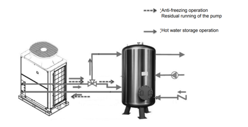
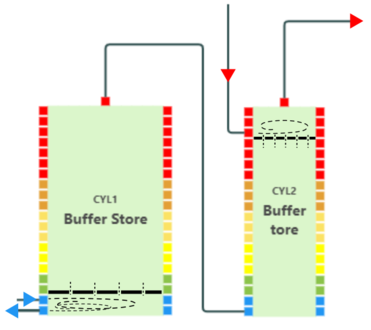
Because of the need for (1) the heat pump defrost circuit to go through the store, and (2) the stability of the output from the heat pump is unknown and could do with some buffering via the top of the buffer store, it will be prudent to fit buffer stores with internal diffuser plates to create chambers to contain turbulence, and maintain stratification. NOTE: When only 1 buffer is to be used, top and bottom plates in same store
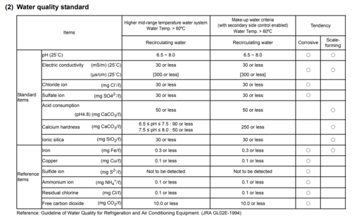
This table shows water quality requirements for the heat pump, and also for a secondary side (not used in SHED). It is important that regular tests are made to ensure this is met. It is also advisable to install water filtration equipment that can maintain these parameters with as little maintenance as possible. Remote monitoring on each of these would be nice.
System Drawings
heatweb_shed_schematic_2e.json Latest Schematic + Electric
heatweb_wiring_shed_heating_stack.json Heating A
heatweb_wiring_shed_heating_a1.json Heating A1
heatweb_wiring_shed_heating_a2.json Heating A2
heatweb_wiring_shed_heating_a3.json Heating A3
heatweb_wiring_shed_heating_a4.json Heating A4
heatweb_shed_wiring_heat_in.json Wiring Heat Input Panel
heatweb_shed_wiring_heat_pump.json Wiring Heat Pump
heatweb_shed_dhw.json DHW Assembly
heatweb_shed_wiring_dhw.json DHW Wiring
heatweb_shed_wiring_coms.json Wiring Comms
Controls Strategy
Heat Pump Control
- Control of the CO2 heat pump is based on recovery of the associated 500 litre buffer store.
- Temperature sensors in the buffer store at different positions provide signals to the heat pump controls.
- The heat pump will start reheating the buffer when there is a set volume of water ready to reheat and continue until the buffer is fully heated
- The temperature the heat pump heats water to is set using an external control signal, and will be driven by required temperatures to deliver hot water and central heating, between 60C and 85C.
- Temperature requirements will be calculated from external air temperatures.
- The power output of the heat pump may also be externally controlled.
- In order to minimise the number of firing cycles per day, the power will be modulated in order to achieve a steady state where possible, reverting to batch loading where loads are lower than minimum heat pump output.
- The COP off the heat pump will be calculated from measuring both the electrical input and the heat output.
- Operational strategies may be adjusted based on feedback from COP calculations.
Domestic Hot Water (DHW)
- Domestic hot water is provided by a 90 litre unvented hot water cylinder.
- The hot water cylinder is located as near to outlets as possible to minimise tap delay.
- The hot water cylinder is fitted with multiple temperature sensors.
- DHW is heated by the use of a plate heat exchanger assembly (an HIU), with cold water pumped from the base of the cylinder through the plate heat exchanger where it is heated to target temperatures and fed into the top of the cylinder, heating variable quantities from the top down.
- The plate heat exchanger if fed with hot primary water from the buffer store, heated by the heat pump.
- The volumes of hot water heated may be adjusted based on DHW requirements (occupancy levels).
- The rate that water is heated may be adjusted by altering the pump speed.
- The rate of reheat will be accelerated as the hot water cylinder empties, reverting to instantaneous DHW generation when the cylinder is almost exhausted.
- The hot water cylinder is fitted with two immersion heaters. One at the bottom to allow heating of the entire cylinder, and one located at the top allowing for rapid reheating of small quantities.
- Use of the upper heating element in partnership with the plate heat exchanger pump allows variable quantities of water to also be heated by the upper electric element alone.
Central Heating
- Central heating is driven by pumping heated water from the buffer store to heat emitters. when there is a demand for heat.
- The central heating pump is switched off when there is no load requirements for either DHW or central heating.
- The flow rate through each heat emitter (radiator or fan convector or panel) is varied in order to achieve required room temperatures.
- Flow rates through heat emitters is controlled by a 0-10v actuator fitted on the return pipe from the emitters, located on a manifold into which all zones return independently.
- In order to eliminate excessive start-up temperatures, heating start times will be adjusted in order to achieve target temperatures by set times. The start times will be calculated based on external air temperatures and system feed-back (optimum start).
Heat Pump Selection
Selection
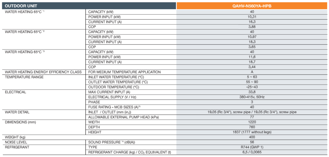
The selected heat pump is a Mitsubishi Electric QAVG 40kW CO2 Air Source Heat Pump.
Specifically designed for commercial sanitary hot water application, where gas boilers, combined heat and power systems (CHP) or electric water heating have been traditionally utilised, the QAHV provides a low carbon solution for hospitals, hotels, leisure centres and student accommodation. Utilising the natural and stable refrigerant CO2 (R744), the environmentally clean solution enables compliance to strict local planning laws and boosts BREEAM points. Compounded by the increasing decarbonisation of the electrical grid and the UK’s commitment to Net Zero 2050, the QAHV provides a high efficiency, low carbon hot water delivery solution with leaving water temperature up to 90°C.
Documentation
![]() QAHV_6PP_AW_v2
QAHV_6PP_AW_v2
![]() QAHV-N560YA-HPB_Service_Manual
QAHV-N560YA-HPB_Service_Manual
![]() QAHV-N560YA-HPB_Install_Manual
QAHV-N560YA-HPB_Install_Manual
![]() QAHV-N560YA-HPB-PI-SHEET
QAHV-N560YA-HPB-PI-SHEET
![]() MELCOBEMS_MINI-PI-Sheet
MELCOBEMS_MINI-PI-Sheet
![]() MELCOBEMS_MINI_A1M_ATW_Modbus_Register_Tables
MELCOBEMS_MINI_A1M_ATW_Modbus_Register_Tables
Technical Specifications
Electric Boiler
Domestic Hot Water
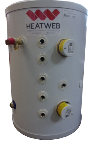
Hot water to be provided using a Storage HIU from Thermal Integration in partnership with a 90 litre unvented cylinder.
Installation
Central Heating
![]() SHED_First_Floor_Heating_Plan.pdf
SHED_First_Floor_Heating_Plan.pdf
![]() SPC-Tilevector-Plus-Low-Water-Temp-Units-Data-Sheet-Iss1.pdf
SPC-Tilevector-Plus-Low-Water-Temp-Units-Data-Sheet-Iss1.pdf
![]() SPC-Thermatile-10-12-IOM-Iss-13.pdf
SPC-Thermatile-10-12-IOM-Iss-13.pdf
![]() Olypia_Splendid_Heater_Technical_Catalogue.pdf
Olypia_Splendid_Heater_Technical_Catalogue.pdf
Room Controllers
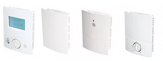
Initial requirement is for:
- temperature, humidity and CO2 sensing.
- hard wired
- preferable Modbus RTU / TCP, or BACNET
- existing units that use 0-10v and resistance can be worked with
 Sontay GS-CO2-S
Suggest SC-S-403000 with:
- temperature, humidity and CO2 sensing.
- PIR sensing
- Modbus RTU or BACnet
- 24v dc
![]() Sc-x-download.pdf
Sc-x-download.pdf
![]() Modbus Registers
Modbus Registers
![]() SC-S Smart Sensor
SC-S Smart Sensor
Return Manifold
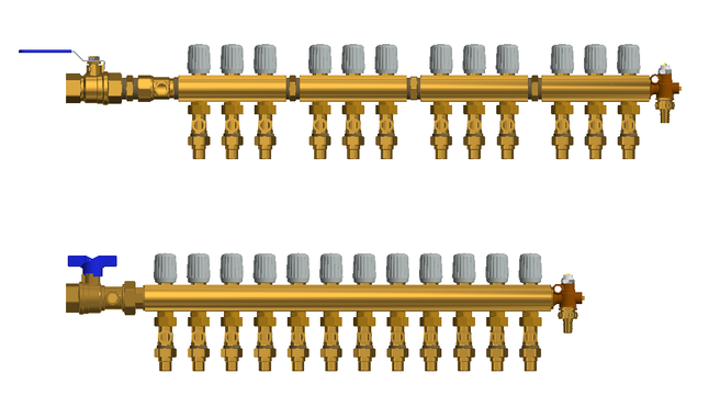
There are up to 24 zones (heat emitters) on the system, controlled by actuators on a return manifold.
The flow pipe is common, branching where appropriate to heat emitters.
Radiators are fitted with isolation only, with all flow control performed on the return manifolds.
Room thermostats PID control to room temperature, setting a return temperature as output. If the room needs to be hotter, the controls raise the return temperature. The actuators are then PID controlled to achieve the set return temperatures for each zone. This two stage control prevents excessive return temperatures at startup, and allows better control strategy based on return temperature to be implemented.
Under steady state load, return temperatures should be around 30C. Increasing flow temperatures will reduce return temperatures, and as such it possible to meet an increased startup load by increasing flow temperatures (charging the buffer store to 75C overnight) to achieve higher emitter outputs for the same return temperature.
It should be possible to decide the return temperature in advance, and then achieve this purely through managing heat pump supply temperatures. One can take the return temperature setpoints from heating control to slowly adjust the heat pump output temperature. If we desire a return temperature of 25C, to achieve a COP nearer 4, then, when the average return temperature setpoint climbs over 25C the system would increase heat pump temperatures, resulting in increased heat input, resulting in a drop in return setpoint. Some investigation needs to be done into determining the most efficient flow/return temperature conditions for a given outside air temperature, with a possibility of achieving significant efficiency gains in low heating seasons.
With all flow limitation performed by actuators, it is also possible to achieve higher startup water velocities, up to the limit of pipework pressure loss. This has advantages in clearing air and dirt. As part of the standard controls we will perform an occasional zone by zone flushing and exercising operation.
(2x) 4 x 3 way manifolds are been used for reasons of availability.
Radiator Outputs
https://www.stelrad.com/radiators/standard-steel-radiators/classic-compact/
The following outputs are based on a 33C delta T.
This comes from a 75/30C profile, with an average temperature of 52.5C, giving a 33C difference to room temperatures.
The heat pump envelope allows loads to be increased 40% over these values if ever needed.
Convector Outputs
These are existing units to me made use of.
Pipework Selection
Pipework is to be in John Guest Speedfit barrier pipe.
10mm pipework, with a velocity of 0.042 litres/second provides 1.95 kW at an 11C drop.
We are running radiators at roughly 33C drop, three times this, so 10mm pipe can achieve a heating load of 6kW through 10mm pipe.
At peak peak, with heat pump running up to 90C, and return at 35C, it should be possible to achieve just over 9kW.
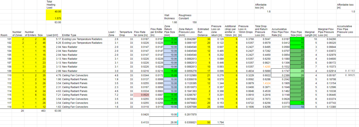
The following spreadsheet calculates pressure drops along central heating return pipes, for each zone.
7 of the zones require a 15mm return pipe. The remainder can be in 10mm.
Flow pipes are only ever in 10mm for 3m or less, when connecting to a heat emitter, until they join the main flow pipe, which is in 15, 22 and 28mm depending on number of zones the pipe feeds.
Pump Selection
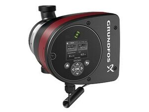
Magna3 25-120
Parts List
The following parts are key to operation of the system.
| Item | Quantity | Notes | Supplied | Invoiced |
|---|---|---|---|---|
| CO2 Air Source Heat Pump & Accessories | 1 | |||
| 500 litre Buffer Store | 1 | 15/12/22 | 6094 | |
| 90 litre Direct Unvented Cylinder | 1 | 18/1/23 | 6095 | |
| Plate Heat Exchanger Recovery Unit (inc pump) | 1 | |||
| Magna 3 Pump 25-120 | 1 | 15/12/22 | 6094 | |
| CIM200 Modbus Card for Magna3 | 1 | Covered under project | ||
| 12 Port Manifold | 2 | Covered under project | 14/12/22 | 6094 |
| 0-10V Actuators and Adaptor rings | 24 | Covered under project | 18/1/23 | |
| NTC Temperature Sensors (Short immersion 70HSF52727) | 24 | Covered under project | ||
| Static Pressure Sensors (0-6 Bar 70200217) | 5 | Covered under project | 18/1/23 | |
| Magnaclean Air & Dirt Separator | 1 | Basic model | ||
| Primary Expansion Vessel 50 litres | 1 | 15/12/22 | 6094 | |
| Sealed System Kit | 1 | 15/12/22 | 6094 | |
| Heat Meters (Zenner C5 with M-Bus) | 3 | Covered under project | 23/1/23 | |
| Heat & Cooling Meter | 1 | Covered under project | 23/1/23 | |
| DPCV (Differential Pressure Control Valve 22mm) | 2 | 15/12/22 | 6094 | |
| Radiators | ||||
| Panel Heaters | ||||
| Fan Convectors | ||||
| Three Port Control Valve, Modulating 0-10v, 22mm | 1 | Covered under project | 23/1/23 | |
| Sontay smart space sensor, with Temp, Humidity, CO2, LCD & Setpoint | 20 | Covered under project | 23 x Back Plates supplied 18/1/23 | 6095 |
| Sontay smart space sensor, with Temp, Humidity, CO2, PIR & Setpoint | 1 | Covered under project | ||
| Sontay smart outside sensor, with Rad Shield Temp & Humidity | 1 | Covered under project | ||
| DS18B20 Sensors (For temporarily fitting in place of Sontay sensors) | 22 | Covered under project | 18/1/23 | 6095 |
BEMS Heat Input Panel including:
|
1 | Covered under project | Enclosure supplied 18/1/23 | |
BEMS Central Heating 12 Zone Panel including:
|
2 | Covered under project | Enclosures supplied 18/1/23 | |
BEMS Domestic Hot Water Panel including:
|
1 | Covered under project | Enclosure supplied 18/1/23 | |
| Pipework and Insulation | ||||
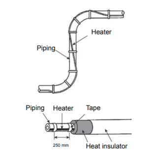
| Trace heating for external heat pump pipework |
The following parts are optional, to achieve higher standards more suited to heat networks than single client systems.
| Item | Quantity | Notes |
|---|---|---|
| Pressurisation Set | 1 | |
System Benefits
The installation of a CO2 Heat Pump is not as simple as using basic electric heaters and an electric unvented cylinder, however the CO2 system offers a COP performance of 3+, translating to a 67% saving in electrical consumption and running costs.
The following points should be considered in the choice of whether to use CO2 heat pumps in the SHED or to go the easier route.
- COP of 3+ provides a 67% saving in both electrical consumption, costs and CO2 emissions. For every unit of electricity used, a further two units will be generated for 'free'.
- The system offers the ability to deliver outputs far in excess of the calculated peak loads, and will be able to deliver services on the coldest of days.
- Reduced peak electrical loads / supplies.
- The ability to time heat generation with cheap rate electrical tariffs (e.g. Economy 10/2000) - up to capacity of storage.
- Centrally driven, with the possibility to add in additional heat sources in future, including solar thermal or biomass . The system is future proofed for any eventuality.
- While the SHED is a single building, the layout and loads are comparable to a heat network consisting of up to 20 properties (depending on size). CO2 heat pumps have never been used on a heat network because of the historic temperature profiles, however recent advances in heat network management (central heating control) have allowed us to achieve compatible temperatures and the technology is ready for field trials. It is expected that the SHED will demonstrate that it is not only possible to heat properties and generate hot water, but also to reduce the costs per property to under £3000, which would be a game changer for the switch to zero carbon, and would come in under the current government grants of £5000 per property.
- If the SHED project were not to go ahead using CO2 technology, there would be at least another year lost - for the whole planet - in the race to offer better lower cost solutions to the current housing stock connected to central boiler plants. While the cost of this cannot be put into £, it is important to understand that with energy costs rising rapidly, a solution that can save up to 60% of energy consumption (compared to direct electric) and 50%+ of installation costs (compared to individual heat pumps) will be massive.
- This time next year the Welsh Government may have a working solution that can be applied worldwide. If the SHED project were not to go ahead, this time next year we will be no further ahead.
- The planned tests on the various heat emitters in the SHED will be of significant importance to all future heat networks, with clear and documented practices and performances.
- The majority of material costs are covered by the project, offering the client (the Welsh Government) the best value for money of any Heat Pump scheme ever run.
- The project is receiving free design consultancy of a type that would normally cost tens of thousands of £.
Top-Up Load
Achieving loads over 40kW
The following link opens a calculation for the loads on the system.
https://hw7.ddns.net/ui/hndesign?loadCID=QmXECSyszAb1fWrz6y3kjHF2wpmjqPGZC583ZAdcu2MSXZ
The CO2 heat pumps come in 40kW outputs, however it may become necessary to achieve higher heating outputs , with a figure of 62kW when it is -3C outside.
The additional 22kW output would need to be satisfied using a top-up heater, or a second heat pump (resulting in significant oversizing).
22kW can easily be achieved with a small electric boiler, at a fraction of the cost of a heat pump, however the efficiency is 30% that of a heat pump, where the COP provides additional heat.
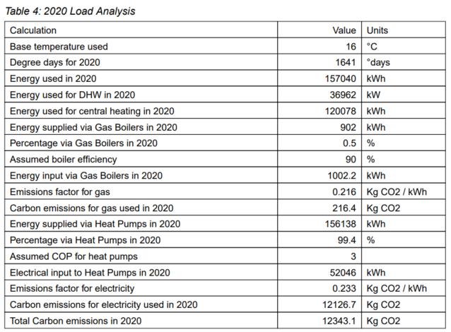
To understand the impact it is necessary to look at the loads using historical weather data to estimate the percentage of heat required from a top-up system. The following graphs shows the output from this calculation, with 99.4% of the total annual energy coming from heat pumps and the remaining 0.6% coming from top-up on the coldest days.
So from a running costs perspective, one would expect to pay 1.2% more per year than if one were using purely heat pumps.
To counter this additional cost one must then consider:
- Significantly lower maintenance costs for an electric boiler than a heat pump system.
- Very large saving on initial capital and installation costs. It would take decades to recoup the cost of a second heat pump based on saving 1.2%, if at all given the extra maintenance costs.
- Potential small gains in very low heating season where are no external pipe losses (flow from heat pump)
- The embedded carbon footprint of an electric boiler is far less than a 40kW heat pump, even a CO2 one, so any carbon savings need to first offset the additional inherent carbon content.
- Space. A second 40kW heat pump requires more than twice the space, as well as double the air supply.
From this exercise it appears that a general design rule could be to design for 2/3 of peak output (66%) on heat pumps, and 1/3 (33%) on direct electric.
Furthermore, it makes sense to make additional redundancy supplies also direct electric, as they would not normally be used, so the investment in a heat pump cannot be justified purely for backup. Something near a 50/50 split, with 50% heat pumps, 25% top-up electric, and 25% redundant electric backup. This makes for a far leaner design, still capable of achieving the required performance levels with redundancy, but overall saving space, cost, and CO2.
It should also be noted that the use of a top-up heating element reduces the need for the heat pump to reach the higher temperatures. At peak load, with a return of 30C, a heat pump can do 66% of load, taking water from 30C to 60C, with the top-up taking it to 75C, doing the final 33% of load. Therefore, the heat pump need only to achieve 60-65C. Radiators do not need uprating because of the higher flow temperatures in colder weather, but return performance is still very important, as a higher return temperature will reduce the percentage the heat pump can assume.
Note: With hindsight, we could have supplied a buffer store with two 12kW immersion batteries fitted in the top for this purpose, potentially avoiding the need for a separate electric boiler and pump. However it is also desirable to use a dedicated electric boiler along with supporting manufactures warranty.
Bivalent Systems for Heat Networks
The following designs show the impact of a single 40kW heat pump on various numbers of properties. This is unrelated to the SHED, however is shown in order to give the reader a feel for the impact of even a single heat pump on real-world loads.
Each property is 2 bedroom 3 person, and 4kW heating load.
Topping up boilers are included to achieve peak loads.
| Properties | % Heat Pump | Design Link |
|---|---|---|
| 20 x 2B3P | 99.9% | https://hw7.ddns.net/ui/hndesign?loadCID=QmNg4trTmoxkD35qj4eBWd1exKwKfbVpP3jRNgEQwZn4qB |
| 30 x 2B3P | 94.6% | https://hw7.ddns.net/ui/hndesign?loadCID=QmXz5H1sdV5F1juQrQc71PLjdWCPWkHhqHkitGbC8o8B9z |
| 40 x 2B3P | 83.6% | https://hw7.ddns.net/ui/hndesign?loadCID=QmPgBB6jSXehwP2ZYp7LcZNQeEyXggQM4FPgcgdQWQgZVc |
This graph shows how the vast majority of load (for 2021) is driven by heat pumps (blue & orange), with boilers (green) used to top up.
Operational Data Policy
This section manages any policies, requirements and plans on data storage, user access, and MQTT permissions.
- Operational data to be logged in real-time
- Recent data points stored in controller memory
- Options to write data logs to hard drive
- Options to write data logs to IPFS file system (encryption policy to discuss)
- Use of both crude and fine grained security settings by user, network, device, data type and key (MQTT ACL file functionality)
- This Wiki project page will detail performance data for as long as SHED is in 'public' mode
- A Private Wiki will run on the LAN with levels of user access control. This will act as:
- the primary user interface,
- storage space for logs locally,
- documentation repository.
- backups of controller software (so new controllers can be cloned)
- VPN access to system
- SSL https certificates on any exposed portals, and on MQTT services.
- None of these core functions to require any licences or software costs (just add internet)
