Difference between revisions of "Buffer Store Control"
| Line 24: | Line 24: | ||
*Makes possible the implementation of storage management and sequencing based on volatile fuel prices using predicted loads | *Makes possible the implementation of storage management and sequencing based on volatile fuel prices using predicted loads | ||
== | == Hydraulic Design == | ||
This application starts with a definition of the system to be controlled. This is done through a schematic design that in turn leads to control points, logic, and a parts list. | |||
The following schematic was generated using our open-source [http://heatweb.co.uk/w/index.php?title=Heat_Network_Designer Heat Network Designer software]. | The following schematic was generated using our open-source [http://heatweb.co.uk/w/index.php?title=Heat_Network_Designer Heat Network Designer software]. | ||
Revision as of 13:46, 24 May 2022
The new Heat Network Guidance from CIBSE, along with CP1, have been clear about the correct way that buffer stores should be implemented in systems.
The methods laid out in guidance require boilers and heat sources to be sequenced from storage, rather than temperature error , and they must also have loading valves. These functions can prove a challenge to the best BMS installers, so the use of a standardised open-source controls library and hardware interface makes a great deal of sense, allowing the finer detail to improve (evolve) over time, rather than trying to reinvent the wheel on every installation based on an individual's understanding of both guidance and BMS software.
This controller function is suitable for domestic and commercial storage systems. It can be used stand-alone, in groups, or as an interface for BMS systems.
Functionality
- Heat sources are assigned an order, representing the preferred order in which they fire, with 1 being the lead.
- Uncontrolled heat sources, such as solar thermal, has an order of 0. Heat will be taken if available and safety controls allow.
- Heat sources with the same order will be run in duty/standby and rotated, pulling in the next in order as required.
- Heat sources are fired up according to store depletion, both on volume remaining and rate of depletion.
- Heat sources may be exercised after a period of inactivity, regardless of order.
- Modulation will be applied to heat sources where possible to match loads and minimise cycling.
- Low load buffering mode to minimise cycling.
- Timing functions can be applied.
- Includes functions for override of non-critical loads, such as central heating, when store close to empty.
- Includes functions for activation of heat dump circuits for solar thermal and biomass.
- Includes functions for boiler loading valve and pump control (with DP switch or sensor).
- Includes functions for network tempering valve control.
- BMS integration via Modbus RTU or IP.
- Includes functions for M-Bus/Modbus heat meter reading.
- Includes alarm functions for low/high temperature, low/high pressure, low storage, failure of heat sources.
- Makes possible the implementation of storage management and sequencing based on volatile fuel prices using predicted loads
Hydraulic Design
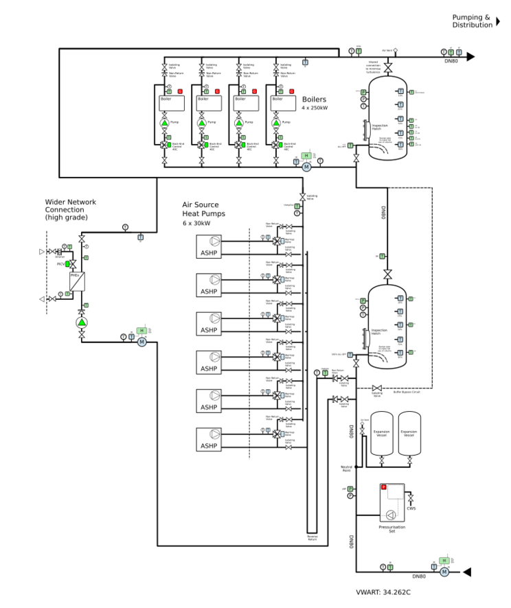
This application starts with a definition of the system to be controlled. This is done through a schematic design that in turn leads to control points, logic, and a parts list.
The following schematic was generated using our open-source Heat Network Designer software.
