The new Heat Network Guidance from CIBSE, along with CP1, have been clear about the correct way that buffer stores should be implemented in systems.
The methods laid out in guidance require boilers and heat sources to be sequenced from storage, rather than temperature error , and they must also have loading valves. These functions can prove a challenge to the best BMS installers, so the use of a standardised open-source controls library and hardware interface makes a great deal of sense, allowing the finer detail to improve (evolve) over time, rather than trying to reinvent the wheel on every installation based on an individual's understanding of both guidance and BMS software, within contract time and budget constraints.
This controller function is suitable for domestic and commercial storage systems. It can be used stand-alone, in groups, or as an interface for BMS systems.
Functionality
- Heat sources are assigned an order, representing the preferred order in which they fire, with 1 being the lead.
- Uncontrolled heat sources, such as solar thermal, has an order of 0. Heat will be taken if available and safety controls allow.
- Heat sources with the same order will be run in duty/standby and rotated, pulling in the next in order as required.
- Heat sources are fired up according to store depletion, both on volume remaining and rate of depletion.
- Heat sources may be exercised after a period of inactivity, regardless of order.
- Modulation will be applied to heat sources where possible to match loads and minimise cycling.
- Low load buffering mode to minimise cycling.
- Timing functions can be applied.
- Includes functions for override of non-critical loads, such as central heating, when store close to empty.
- Includes functions for activation of heat dump circuits for solar thermal and biomass.
- Includes functions for boiler loading valve and pump control (with DP switch or sensor).
- Includes functions for network tempering valve control.
- BMS integration via Modbus RTU or IP.
- Includes functions for M-Bus/Modbus heat meter reading.
- Includes alarm functions for low/high temperature, low/high pressure, low storage, failure of heat sources.
- Makes possible the implementation of storage management and sequencing based on volatile fuel prices using predicted loads
Hydraulic & Wiring Layouts
{ "class": "GraphLinksModel",
  "copiesArrays": true,
  "copiesArrayObjects": true,
  "linkFromPortIdProperty": "fromPort",
  "linkToPortIdProperty": "toPort",
  "nodeDataArray": [
{"key":"CYL1","name":"Buffer \nStore","loc":"-25.574964750701383 196.3160717356572","leftArray":[{"portColor":"#ff0000","portId":"left0"},{"portColor":"#ff0000","portId":"left1"},{"portId":"left2","portColor":"#ff0000"},{"portId":"left3","portColor":"#ff0000"},{"portId":"left4","portColor":"#ff0000"},{"portId":"left5","portColor":"#ff0000"},{"portId":"left6","portColor":"#ff0000"},{"portId":"left7","portColor":"#e39f35"},{"portId":"left8","portColor":"#e39f35"},{"portId":"left9","portColor":"#e39f35"},{"portId":"left10","portColor":"#fbe264"},{"portId":"left11","portColor":"#fbe264"},{"portId":"left12","portColor":"#fbe264"},{"portId":"left13","portColor":"#ffff00"},{"portId":"left14","portColor":"#ffff00"},{"portId":"left15","portColor":"#ffff00"},{"portId":"left16","portColor":"#8bc34a"},{"portId":"left17","portColor":"#8bc34a"},{"portId":"left18","portColor":"#2196f3"},{"portId":"left19","portColor":"#2196f3"}],"topArray":[{"portColor":"#ffffff","portId":"top0"},{"portId":"top1","portColor":"#ffffff"},{"portId":"top2","portColor":"#ffffff"},{"portId":"top3","portColor":"#ffffff"},{"portId":"top4","portColor":"#ffffff"},{"portId":"top5","portColor":"#ff0000"},{"portId":"top6","portColor":"#ffffff"},{"portId":"top7","portColor":"#ffffff"},{"portId":"top8","portColor":"#ffffff"},{"portId":"top9","portColor":"#ffffff"},{"portId":"top10","portColor":"#ffffff"}],"bottomArray":[],"rightArray":[{"portColor":"#ff0000","portId":"right0"},{"portColor":"#ff0000","portId":"right1"},{"portId":"right2","portColor":"#ff0000"},{"portId":"right3","portColor":"#ff0000"},{"portId":"right4","portColor":"#ff0000"},{"portId":"right5","portColor":"#ff0000"},{"portId":"right6","portColor":"#ff0000"},{"portId":"right7","portColor":"#e39f35"},{"portId":"right8","portColor":"#e39f35"},{"portId":"right9","portColor":"#e39f35"},{"portId":"right10","portColor":"#fbe264"},{"portId":"right11","portColor":"#fbe264"},{"portId":"right12","portColor":"#fbe264"},{"portId":"right13","portColor":"#ffff00"},{"portId":"right14","portColor":"#ffff00"},{"portId":"right15","portColor":"#ffff00"},{"portId":"right16","portColor":"#8bc34a"},{"portId":"right17","portColor":"#8bc34a"},{"portId":"right18","portColor":"#2196f3"},{"portId":"right19","portColor":"#2196f3"}]},
{"name":"Loading\nValve","leftArray":[{"portId":"left0","portColor":"#d6effc"}],"rightArray":[{"portId":"right1","portColor":"#66d6d1"}],"topArray":[{"portId":"top0","portColor":"#fae3d7"}],"bottomArray":[],"key":"loadV","loc":"-336.11505660615677 328.04419652363913"},
{"name":"F+E","leftArray":[],"rightArray":[],"topArray":[{"portId":"top0","portColor":"#ffffff"}],"bottomArray":[{"portId":"bottom0","portColor":"#6cafdb"}],"key":"header","loc":"-129.74200000000008 -23.564875000000058"},
{"name":"Underfloor \nHeating","leftArray":[{"portId":"left0","portColor":"#fadfe5"},{"portId":"left1","portColor":"#6cafdb"}],"rightArray":[],"topArray":[],"bottomArray":[{"portId":"bottom0","portColor":"#fadfe5"},{"portId":"bottom1","portColor":"#6cafdb"},{"portId":"bottom2","portColor":"#fadfe5"},{"portId":"bottom3","portColor":"#6cafdb"},{"portId":"bottom4","portColor":"#fae3d7"},{"portId":"bottom5","portColor":"#6cafdb"},{"portId":"bottom6","portColor":"#fae3d7"},{"portId":"bottom7","portColor":"#6cafdb"},{"portId":"bottom8","portColor":"#fae3d7"},{"portId":"bottom9","portColor":"#6cafdb"}],"key":"ufh","loc":"257 307.125"},
{"name":"Radiators","leftArray":[{"portId":"left0","portColor":"#ffffff"},{"portId":"left1","portColor":"#ffffff"},{"portId":"left2","portColor":"#ffffff"},{"portId":"left3","portColor":"#ffffff"},{"portId":"left4","portColor":"#fae3d7"}],"rightArray":[{"portId":"right0","portColor":"#ffffff"},{"portId":"right1","portColor":"#ffffff"},{"portId":"right2","portColor":"#ffffff"},{"portId":"right3","portColor":"#ffffff"},{"portId":"right4","portColor":"#6cafdb"}],"topArray":[],"bottomArray":[],"key":"radsUp","loc":"344 57.125"},
{"name":"Pump","leftArray":[{"portId":"left0","portColor":"#fae3d7"}],"rightArray":[{"portId":"right4","portColor":"#fae3d7"}],"topArray":[],"bottomArray":[],"key":"pumpCH","loc":"154 125.125"},
{"name":"Radiators","leftArray":[{"portId":"left0","portColor":"#ffffff"},{"portId":"left1","portColor":"#ffffff"},{"portId":"left2","portColor":"#ffffff"},{"portId":"left3","portColor":"#ffffff"},{"portId":"left4","portColor":"#fae3d7"}],"rightArray":[{"portId":"right0","portColor":"#ffffff"},{"portId":"right1","portColor":"#ffffff"},{"portId":"right2","portColor":"#ffffff"},{"portId":"right3","portColor":"#ffffff"},{"portId":"right4","portColor":"#66d6d1"}],"topArray":[],"bottomArray":[],"key":"radsDown","loc":"325 186.125"},
{"name":"Pump","leftArray":[{"portId":"left0","portColor":"#fae3d7"}],"rightArray":[{"portId":"right4","portColor":"#ebe3fc"}],"topArray":[],"bottomArray":[],"key":"pumpB","loc":"-453 328.125"},
{"name":"Biomass Boiler","leftArray":[],"rightArray":[{"portId":"right0","portColor":"#fadfe5"},{"portId":"right1","portColor":"#66d6d1"}],"topArray":[],"bottomArray":[],"key":"boiler1","loc":"-608.7532829862678 271.6673070407662"},
{"name":"Wood \nBurner","leftArray":[],"rightArray":[{"portId":"right1","portColor":"#fadfe5"},{"portId":"right0","portColor":"#d6effc"}],"topArray":[],"bottomArray":[],"key":"wb1","loc":"-275 436.125"},
{"name":"Pump","leftArray":[{"portId":"left0","portColor":"#6cafdb"}],"rightArray":[{"portId":"right4","portColor":"#6cafdb"}],"topArray":[],"bottomArray":[],"key":"pumpHX","loc":"-328 201.125"},
{"name":"PHE","leftArray":[],"rightArray":[],"topArray":[{"portId":"top0","portColor":"#fadfe5"},{"portId":"top1","portColor":"#fae3d7"}],"bottomArray":[{"portId":"bottom0","portColor":"#d6effc"},{"portId":"bottom1","portColor":"#6cafdb"}],"key":"HX","loc":"-452 150.125"},
{"name":"Taps","leftArray":[],"rightArray":[{"portId":"right0","portColor":"#fadfe5"}],"topArray":[],"bottomArray":[],"key":"DHW","loc":"-661 96.125"},
{"name":"Flow\nSensor","leftArray":[{"portId":"left0","portColor":"#66d6d1"}],"rightArray":[{"portId":"right0","portColor":"#d6effc"}],"topArray":[],"bottomArray":[],"key":"FS","loc":"-556 173.125"},
{"name":"Mains","leftArray":[],"rightArray":[{"portId":"right0","portColor":"#6cafdb"}],"topArray":[],"bottomArray":[],"key":"CWS","loc":"-661 173.125"},
{"name":"Living\nRoom","leftArray":[],"rightArray":[],"topArray":[{"portId":"top0","portColor":"#fae3d7"},{"portId":"top1","portColor":"#6cafdb"},{"portId":"top2","portColor":"#fadfe5"},{"portId":"top3","portColor":"#6cafdb"}],"bottomArray":[],"key":"zone1","loc":"141 481.125"},
{"name":"Kitchen","leftArray":[],"rightArray":[],"topArray":[{"portId":"top0","portColor":"#fae3d7"},{"portId":"top1","portColor":"#6cafdb"}],"bottomArray":[],"key":"zone2","loc":"257 480.125"},
{"name":"Hall","leftArray":[],"rightArray":[],"topArray":[{"portId":"top0","portColor":"#fae3d7"},{"portId":"top1","portColor":"#6cafdb"}],"bottomArray":[],"key":"zone3","loc":"339 478.125"},
{"name":"Dining\nRoom","leftArray":[],"rightArray":[],"topArray":[{"portId":"top0","portColor":"#fae3d7"},{"portId":"top1","portColor":"#6cafdb"}],"bottomArray":[],"key":"zone4","loc":"416 476.125"},
{"name":"","leftArray":[],"rightArray":[{"portId":"right1","portColor":"#fadfe5"},{"portId":"right0","portColor":"#d6effc"}],"topArray":[],"bottomArray":[],"key":"Solar Coil","loc":"-47 261.625"},
{"name":"Solar Thermal","leftArray":[{"portId":"left0","portColor":"#fadfe5"},{"portId":"left1","portColor":"#ffffff"},{"portId":"left2","portColor":"#ffffff"},{"portId":"left3","portColor":"#ffffff"},{"portId":"left4","portColor":"#d6effc"}],"rightArray":[{"portId":"right0","portColor":"#ffffff"},{"portId":"right1","portColor":"#ffffff"},{"portId":"right2","portColor":"#ffffff"},{"portId":"right3","portColor":"#ffffff"}],"topArray":[],"bottomArray":[],"key":"solar","loc":"173 -41.875"}
],
  "linkDataArray": [
{"from":"CYL1","to":"pumpCH","fromPort":"right5","toPort":"left0","points":[37.42503524929862,151.3160717356572,91.42503524929862,151.3160717356572,92,151.3160717356572,92,125.125,106,125.125,116,125.125]},
{"from":"pumpCH","to":"radsUp","fromPort":"right4","toPort":"left4","points":[192,125.125,206,125.125,262.345703125,125.125,262.345703125,77.125,286.69140625,77.125,296.69140625,77.125]},
{"from":"radsUp","to":"CYL1","fromPort":"right4","toPort":"right15","points":[391.30859375,77.125,401.30859375,77.125,401.30859375,251.3160717356572,286.3668144996493,251.3160717356572,171.42503524929862,251.3160717356572,37.42503524929862,251.3160717356572]},
{"from":"pumpCH","to":"radsDown","fromPort":"right4","toPort":"left4","points":[192,125.125,202,125.125,232.845703125,125.125,232.845703125,206.125,231.69140625,206.125,277.69140625,206.125]},
{"from":"radsDown","to":"CYL1","fromPort":"right4","toPort":"right15","points":[372.30859375,206.125,382.30859375,206.125,382.30859375,251.3160717356572,276.8668144996493,251.3160717356572,171.42503524929862,251.3160717356572,37.42503524929862,251.3160717356572]},
{"from":"CYL1","to":"ufh","fromPort":"right10","toPort":"left0","points":[37.42503524929862,201.3160717356572,119.42503524929862,201.3160717356572,168.2125176246493,201.3160717356572,168.2125176246493,302.125,185,302.125,199,302.125]},
{"from":"ufh","to":"CYL1","fromPort":"left1","toPort":"right18","points":[199,312.125,177,312.125,114.21251762464931,312.125,114.21251762464931,281.3160717356572,55.42503524929862,281.3160717356572,37.42503524929862,281.3160717356572]},
{"from":"CYL1","to":"loadV","fromPort":"left23","toPort":"right1","points":[-88.57496475070138,192.3160717356572,-98.57496475070138,192.3160717356572,-177.34501067842908,192.3160717356572,-177.34501067842908,328.04419652363913,-288.11505660615677,328.04419652363913,-298.11505660615677,328.04419652363913]},
{"from":"pumpB","to":"boiler1","fromPort":"left0","toPort":"right1","points":[-491,328.125,-505,328.125,-521.7047664931339,328.125,-521.7047664931339,276.6673070407662,-534.4095329862678,276.6673070407662,-544.4095329862678,276.6673070407662]},
{"from":"loadV","to":"pumpB","fromPort":"left0","toPort":"right4","points":[-374.11505660615677,328.04419652363913,-384.11505660615677,328.04419652363913,-394.55752830307836,328.04419652363913,-394.55752830307836,328.125,-401,328.125,-415,328.125]},
{"from":"boiler1","to":"loadV","fromPort":"right0","toPort":"top0","points":[-544.4095329862678,266.6673070407662,-526.4095329862678,266.6673070407662,-336.11505660615677,266.6673070407662,-336.11505660615677,271.3557517822027,-336.11505660615677,276.04419652363913,-336.11505660615677,290.04419652363913]},
{"from":"CYL1","to":"header","fromPort":"top5","toPort":"top0","points":[-25.574964750701383,88.3160717356572,-25.574964750701383,34.316071735657204,-25.574964750701383,-71.56487500000006,-77.65848237535073,-71.56487500000006,-129.74200000000008,-71.56487500000006,-129.74200000000008,-61.56487500000006]},
{"from":"header","to":"CYL1","fromPort":"bottom0","toPort":"left18","points":[-129.74200000000008,14.435124999999942,-129.74200000000008,24.435124999999942,-129.74200000000008,68.37559836782857,-129.74200000000008,281.3160717356572,-88.57496475070138,281.3160717356572]},
{"from":"wb1","to":"CYL1","fromPort":"right1","toPort":"left6","points":[-236.66357421875,431.125,-222.66357421875,431.125,-196.6192694847257,431.125,-196.6192694847257,161.3160717356572,-202.57496475070138,161.3160717356572,-88.57496475070138,161.3160717356572]},
{"from":"CYL1","to":"wb1","fromPort":"left17","toPort":"right0","points":[-88.57496475070138,271.3160717356572,-114.57496475070138,271.3160717356572,-162.6192694847257,271.3160717356572,-162.6192694847257,441.125,-214.66357421875,441.125,-236.66357421875,441.125]},
{"from":"pumpHX","to":"CYL1","fromPort":"right4","toPort":"left19","points":[-290,201.125,-280,201.125,-221,201.125,-221,291.3160717356572,-254.57496475070138,291.3160717356572,-88.57496475070138,291.3160717356572]},
{"from":"CYL1","to":"HX","fromPort":"left0","toPort":"top1","points":[-88.57496475070138,101.3160717356572,-250.57496475070138,101.3160717356572,-447,101.3160717356572,-447,101.7205358678286,-447,102.125,-447,112.125]},
{"from":"CYL1","to":"boiler1","fromPort":"left1","toPort":"right0","points":[-88.57496475070138,111.3160717356572,-242.57496475070138,111.3160717356572,-244,111.3160717356572,-244,266.6673070407662,-530.4095329862678,266.6673070407662,-544.4095329862678,266.6673070407662]},
{"from":"HX","to":"pumpHX","fromPort":"bottom1","toPort":"left0","points":[-447,188.125,-447,198.125,-447,201.125,-413.5,201.125,-380,201.125,-366,201.125]},
{"from":"DHW","to":"HX","fromPort":"right0","toPort":"top0","points":[-623,96.125,-613,96.125,-457,96.125,-457,97.125,-457,98.125,-457,112.125]},
{"from":"FS","to":"HX","fromPort":"right0","toPort":"bottom0","points":[-517.90966796875,173.125,-507.90966796875,173.125,-507.90966796875,173.125,-507.90966796875,204,-457,204,-457,202.125,-457,188.125]},
{"from":"CWS","to":"FS","fromPort":"right0","toPort":"left0","points":[-623,173.125,-613,173.125,-613,173.125,-613,173.125,-604.09033203125,173.125,-594.09033203125,173.125]},
{"from":"ufh","to":"zone1","fromPort":"bottom0","toPort":"top0","points":[212,345.125,212,359.125,212,374.125,126,374.125,126,409.125,126,443.125]},
{"from":"ufh","to":"zone1","fromPort":"bottom1","toPort":"top1","points":[222,345.125,222,367.125,222,386.125,136,386.125,136,417.125,136,443.125]},
{"from":"ufh","to":"zone1","fromPort":"bottom2","toPort":"top2","points":[232,345.125,232,375.125,232,400.125,146,400.125,146,425.125,146,443.125]},
{"from":"ufh","to":"zone1","fromPort":"bottom3","toPort":"top3","points":[242,345.125,242,383.125,242,413.125,156,413.125,156,433.125,156,443.125]},
{"from":"ufh","to":"zone2","fromPort":"bottom4","toPort":"top0","points":[252,345.125,252,395.125,252,425.625,252,425.625,252,424.125,252,442.125]},
{"from":"ufh","to":"zone2","fromPort":"bottom5","toPort":"top1","points":[262,345.125,262,387.125,262,425.625,262,425.625,262,432.125,262,442.125]},
{"from":"ufh","to":"zone3","fromPort":"bottom6","toPort":"top0","points":[272,345.125,272,379.125,272,418.625,334,418.625,334,426.125,334,440.125]},
{"from":"ufh","to":"zone3","fromPort":"bottom7","toPort":"top1","points":[282,345.125,282,371.125,282,410.625,344,410.625,344,418.125,344,440.125]},
{"from":"ufh","to":"zone4","fromPort":"bottom8","toPort":"top0","points":[292,345.125,292,363.125,292,395.125,411,395.125,411,424.125,411,438.125]},
{"from":"ufh","to":"zone4","fromPort":"bottom9","toPort":"top1","points":[302,345.125,302,355.125,302,385.125,421,385.125,421,416.125,421,438.125]},
{"from":"solar","to":"Solar Coil","fromPort":"left4","toPort":"right0","points":[111.2470703125,-21.875,101.2470703125,-21.875,19,-21.875,19,266.625,13.3583984375,266.625,-8.6416015625,266.625]},
{"from":"solar","to":"Solar Coil","fromPort":"left0","toPort":"right1","points":[111.2470703125,-61.875,69.2470703125,-61.875,68,-61.875,68,-61.875,12,-61.875,12,256.625,5.3583984375,256.625,-8.6416015625,256.625]}
]}
The following wiring diagram can be generated from the hydraulic layout above.

{ "class": "GraphLinksModel",
  "copiesArrays": true,
  "copiesArrayObjects": true,
  "linkFromPortIdProperty": "fromPort",
  "linkToPortIdProperty": "toPort",
  "nodeDataArray": [
{"key":"C1","name":"Unit One","image":"/images/c/c1/C2a.svg","loc":"-25.574964750701383 196.3160717356572","leftArray":[{"portId":"left0","portColor":"#000000"},{"portId":"left1","portColor":"#00ff00"},{"portId":"left2","portColor":"#000000"},{"portId":"left3","portColor":"#00ff00"},{"portId":"left4","portColor":"#000000"},{"portId":"left5","portColor":"#00ff00"},{"portId":"left6","portColor":"#000000"},{"portId":"left7","portColor":"#00ff00"},{"portId":"left8","portColor":"#000000"},{"portId":"left9","portColor":"#ffff00"},{"portId":"left10","portColor":"#000000"},{"portId":"left11","portColor":"#ffff00"},{"portId":"left12","portColor":"#000000"},{"portId":"left13","portColor":"#ffff00"},{"portId":"left14","portColor":"#000000"},{"portId":"left15","portColor":"#ffff00"},{"portId":"left16","portColor":"#000000"},{"portId":"left17","portColor":"#00ff00"},{"portId":"left18","portColor":"#000000"},{"portId":"left19","portColor":"#00ff00"},{"portId":"left20","portColor":"#000000"},{"portId":"left21","portColor":"#00ff00"},{"portId":"left22","portColor":"#000000"},{"portId":"left23","portColor":"#00ff00"}],"topArray":[{"portColor":"#ff9800","portId":"top0"},{"portId":"top1","portColor":"#000000"},{"portId":"top2","portColor":"#ffcc00"},{"portId":"top3","portColor":"#000000"}],"bottomArray":[{"portColor":"#000000","portId":"bottom0"},{"portId":"bottom1","portColor":"#00ffff"},{"portId":"bottom2","portColor":"#000000"},{"portId":"bottom3","portColor":"#00ffff"},{"portId":"bottom4","portColor":"#000000"},{"portId":"bottom5","portColor":"#00ffff"},{"portId":"bottom6","portColor":"#000000"},{"portId":"bottom7","portColor":"#00ffff"},{"portId":"bottom8","portColor":"#000000"},{"portId":"bottom9","portColor":"#40aceb"},{"portId":"bottom10","portColor":"#000000"},{"portId":"bottom11","portColor":"#40aceb"},{"portId":"bottom12","portColor":"#000000"},{"portId":"bottom13","portColor":"#40aceb"},{"portId":"bottom14","portColor":"#000000"},{"portId":"bottom15","portColor":"#40aceb"},{"portId":"bottom16","portColor":"#bf6ae3"},{"portId":"bottom17","portColor":"#bf6ae3"},{"portId":"bottom18","portColor":"#bf6ae3"},{"portId":"bottom19","portColor":"#bf6ae3"},{"portId":"bottom20","portColor":"#bf6ae3"},{"portId":"bottom21","portColor":"#bf6ae3"}],"rightArray":[{"portColor":"#000000","portId":"right0"},{"portColor":"#888888","portId":"right1"},{"portId":"right2","portColor":"#888888"},{"portId":"right3","portColor":"#000000"},{"portId":"right4","portColor":"#888888"},{"portId":"right5","portColor":"#888888"},{"portId":"right6","portColor":"#ddddbb"},{"portId":"right7","portColor":"#ddddbb"},{"portId":"right8","portColor":"#8827e7"},{"portId":"right9","portColor":"#000000"},{"portId":"right10","portColor":"#8827e7"},{"portId":"right11","portColor":"#000000"},{"portId":"right12","portColor":"#8827e7"},{"portId":"right13","portColor":"#000000"},{"portId":"right14","portColor":"#8827e7"},{"portId":"right15","portColor":"#000000"},{"portId":"right16","portColor":"#0000ff"},{"portId":"right17","portColor":"#ff0000"},{"portId":"right18","portColor":"#0000ff"},{"portId":"right19","portColor":"#ff0000"},{"portId":"right20","portColor":"#0000ff"},{"portId":"right21","portColor":"#ff0000"},{"portId":"right22","portColor":"#0000ff"},{"portId":"right23","portColor":"#ff0000"}]},
{"name":"NTC10K","leftArray":[],"rightArray":[{"portId":"right0","portColor":"#6cafdb"},{"portId":"right1","portColor":"#66d6d1"}],"topArray":[],"bottomArray":[],"key":"NTC1","loc":"-551.1296205847993 23.48544088160405"},
{"name":"NTC10K","leftArray":[],"rightArray":[{"portId":"right0","portColor":"#6cafdb"},{"portId":"right1","portColor":"#66d6d1"}],"topArray":[],"bottomArray":[],"key":"NTC2","loc":"-468.92462058479913 72.5251239611851"},
{"name":"NTC10K","leftArray":[],"rightArray":[{"portId":"right0","portColor":"#6cafdb"},{"portId":"right1","portColor":"#66d6d1"}],"topArray":[],"bottomArray":[],"key":"NTC3","loc":"-552.1632829862677 117.56480704076617"},
{"name":"Pulsed Flow\nSensor","leftArray":[],"rightArray":[{"portId":"right0","portColor":"#6cafdb"},{"portId":"right1","portColor":"#66d6d1"},{"portId":"right2","portColor":"#d6effc"}],"topArray":[],"bottomArray":[],"key":"FS1","loc":"-367.7961150175177 518.0648070407661"},
{"name":"Room\nThermostat","leftArray":[],"rightArray":[{"portId":"right0","portColor":"#ebe3fc"},{"portId":"right1","portColor":"#d6effc"}],"topArray":[],"bottomArray":[],"key":"stat2","loc":"-371 615.125"},
{"name":"Room\nThermostat","leftArray":[],"rightArray":[{"portId":"right1","portColor":"#d6effc"},{"portId":"right2","portColor":"#d6effc"}],"topArray":[],"bottomArray":[],"key":"stat1","loc":"-263 569.125"},
{"name":"Pressure \nTemp Sensor","leftArray":[],"rightArray":[{"portId":"right1","portColor":"#d6effc"},{"portId":"right2","portColor":"#d6effc"},{"portId":"right0","portColor":"#6cafdb"},{"portId":"right3","portColor":"#d6effc"}],"topArray":[],"bottomArray":[],"key":"RPS1","loc":"-433.137502668535 266.188369363003"},
{"name":"12v Power","leftArray":[{"portId":"left0","portColor":"#fadfe5"},{"portId":"left3","portColor":"#66d6d1"}],"rightArray":[],"topArray":[],"bottomArray":[],"key":"power12","loc":"389 43.125"},
{"name":"NTC10K","leftArray":[],"rightArray":[{"portId":"right0","portColor":"#6cafdb"},{"portId":"right1","portColor":"#66d6d1"}],"topArray":[],"bottomArray":[],"key":"NTC4","loc":"-468.7532829862677 163.6673070407662"},
{"name":"Underfloor Htg\nControl Valve","leftArray":[{"portId":"left0","portColor":"#fadfe5"},{"portId":"left2","portColor":"#d6effc"},{"portId":"left1","portColor":"#ebe3fc"},{"portId":"left3","portColor":"#66d6d1"}],"rightArray":[],"topArray":[],"bottomArray":[],"key":"valveUFH","loc":"436.93441406249985 397.2275"},
{"name":"Heat Meter","leftArray":[{"portId":"left0","portColor":"#fadfe5"},{"portId":"left3","portColor":"#66d6d1"}],"rightArray":[],"topArray":[],"bottomArray":[],"key":"meter1","loc":"434 209.125"},
{"name":"Modbus\nto BMS","leftArray":[{"portId":"left0","portColor":"#fadfe5"},{"portId":"left3","portColor":"#66d6d1"},{"portId":"left1","portColor":"#6cafdb"}],"rightArray":[],"topArray":[],"bottomArray":[],"key":"modbus1","loc":"395 121.125"},
{"name":"Boiler\nPump","leftArray":[{"portId":"left1","portColor":"#ebe3fc"},{"portId":"left2","portColor":"#d6effc"},{"portId":"left3","portColor":"#66d6d1"}],"rightArray":[],"topArray":[],"bottomArray":[],"key":"pumpB","loc":"396.5244140625 471.125"},
{"name":"Heat Meter","leftArray":[{"portId":"left0","portColor":"#fadfe5"},{"portId":"left3","portColor":"#66d6d1"}],"rightArray":[],"topArray":[],"bottomArray":[],"key":"meter2","loc":"569 209.125"},
{"name":"PHE\nPump","leftArray":[{"portId":"left1","portColor":"#ebe3fc"},{"portId":"left2","portColor":"#d6effc"},{"portId":"left3","portColor":"#66d6d1"}],"rightArray":[],"topArray":[],"bottomArray":[],"key":"pumpHX","loc":"226.5244140625 627.125"},
{"name":"Rads\nPump","leftArray":[{"portId":"left1","portColor":"#ebe3fc"},{"portId":"left2","portColor":"#d6effc"},{"portId":"left3","portColor":"#66d6d1"}],"rightArray":[],"topArray":[],"bottomArray":[],"key":"pumpCH2","loc":"476.5244140625 523.125"},
{"name":"Hot Water\nTimer ","leftArray":[],"rightArray":[{"portId":"right0","portColor":"#ebe3fc"},{"portId":"right1","portColor":"#d6effc"}],"topArray":[],"bottomArray":[],"key":"timerDHW2","loc":"-266 664.125"},
{"name":"Underfloor Htg\nRelay Centre","leftArray":[{"portId":"left0","portColor":"#fadfe5"},{"portId":"left1","portColor":"#ebe3fc"}],"rightArray":[{"portId":"right0","portColor":"#eaeef8"}],"topArray":[],"bottomArray":[],"key":"UFH","loc":"433.5244140625 318.125"},
{"name":"Pump","leftArray":[{"portId":"left1","portColor":"#ebe3fc"}],"rightArray":[],"topArray":[],"bottomArray":[],"key":"pumpUFH","loc":"569.5244140625 332.125"},
{"name":"Solar\nPump","leftArray":[{"portId":"left1","portColor":"#ebe3fc"},{"portId":"left2","portColor":"#d6effc"},{"portId":"left3","portColor":"#66d6d1"}],"rightArray":[],"topArray":[],"bottomArray":[],"key":"pumpS","loc":"396.5244140625 576.125"},
{"name":"NTC10K","leftArray":[],"rightArray":[{"portId":"right0","portColor":"#6cafdb"},{"portId":"right1","portColor":"#66d6d1"}],"topArray":[],"bottomArray":[],"key":"NTC5","loc":"-551.7532829862678 210.6673070407662"},
{"name":"NTC10K","leftArray":[],"rightArray":[{"portId":"right0","portColor":"#6cafdb"},{"portId":"right1","portColor":"#66d6d1"}],"topArray":[],"bottomArray":[],"key":"NTC52","loc":"-550.7532829862678 324.6673070407662"},
{"name":"NTC10K","leftArray":[],"rightArray":[{"portId":"right0","portColor":"#6cafdb"},{"portId":"right1","portColor":"#66d6d1"}],"topArray":[],"bottomArray":[],"key":"NTC12","loc":"-236.82212058479934 478.305440881604"},
{"name":"NTC10K","leftArray":[],"rightArray":[{"portId":"right0","portColor":"#6cafdb"},{"portId":"right1","portColor":"#66d6d1"}],"topArray":[],"bottomArray":[],"key":"NTC22","loc":"-461.9246205847992 374.5251239611851"},
{"name":"NTC10K","leftArray":[],"rightArray":[{"portId":"right0","portColor":"#6cafdb"},{"portId":"right1","portColor":"#66d6d1"}],"topArray":[],"bottomArray":[],"key":"NTC32","loc":"-545.1632829862677 419.56480704076614"}
],
  "linkDataArray": [
{"from":"NTC1","to":"C1","fromPort":"right0","toPort":"left0","points":[-508.78049949104934,18.48544088160405,-490.78049949104934,18.48544088160405,-317.52000000000004,18.48544088160405,-317.52000000000004,81.3160717356572,-157.57496475070138,81.3160717356572,-143.57496475070138,81.3160717356572]},
{"from":"NTC1","to":"C1","fromPort":"right1","toPort":"left1","points":[-508.78049949104934,28.48544088160405,-498.78049949104934,28.48544088160405,-328.5450000000001,28.48544088160405,-328.5450000000001,91.3160717356572,-165.57496475070138,91.3160717356572,-143.57496475070138,91.3160717356572]},
{"from":"C1","to":"NTC2","fromPort":"left2","toPort":"right0","points":[-143.57496475070138,101.3160717356572,-173.57496475070138,101.3160717356572,-338.46750000000003,101.3160717356572,-338.46750000000003,67.5251239611851,-406.57549949104913,67.5251239611851,-424.57549949104913,67.5251239611851]},
{"from":"C1","to":"NTC2","fromPort":"left3","toPort":"right1","points":[-143.57496475070138,111.3160717356572,-181.57496475070138,111.3160717356572,-346.18500000000006,111.3160717356572,-346.18500000000006,77.5251239611851,-414.57549949104913,77.5251239611851,-424.57549949104913,77.5251239611851]},
{"from":"C1","to":"NTC3","fromPort":"left4","toPort":"right0","points":[-143.57496475070138,121.3160717356572,-189.57496475070138,121.3160717356572,-354.69456332160956,121.3160717356572,-354.69456332160956,112.56480704076617,-491.81416189251775,112.56480704076617,-509.81416189251775,112.56480704076617]},
{"from":"C1","to":"NTC3","fromPort":"left5","toPort":"right1","points":[-143.57496475070138,131.3160717356572,-197.57496475070138,131.3160717356572,-370.69456332160956,131.3160717356572,-370.69456332160956,122.56480704076617,-499.81416189251775,122.56480704076617,-509.81416189251775,122.56480704076617]},
{"from":"power12","to":"C1","fromPort":"left0","toPort":"top2","points":[338.7314453125,38.125,320.7314453125,38.125,-20.574964750701383,38.125,-20.574964750701383,44.2205358678286,-20.574964750701383,50.316071735657204,-20.574964750701383,68.3160717356572]},
{"from":"power12","to":"C1","fromPort":"left3","toPort":"top3","points":[338.7314453125,48.125,328.7314453125,48.125,-10.574964750701383,48.125,-10.574964750701383,53.2205358678286,-10.574964750701383,58.316071735657204,-10.574964750701383,68.3160717356572]},
{"from":"FS1","to":"C1","fromPort":"right1","toPort":"bottom0","points":[-312.6501189237677,518.0648070407661,-290.6501189237677,518.0648070407661,-130.57496475070138,518.0648070407661,-130.57496475070138,428.19043938821164,-130.57496475070138,338.3160717356572,-130.57496475070138,324.3160717356572]},
{"from":"FS1","to":"C1","fromPort":"right2","toPort":"bottom1","points":[-312.6501189237677,528.0648070407661,-282.6501189237677,528.0648070407661,-120.57496475070138,528.0648070407661,-120.57496475070138,437.19043938821164,-120.57496475070138,346.3160717356572,-120.57496475070138,324.3160717356572]},
{"from":"stat1","to":"C1","fromPort":"right1","toPort":"bottom2","points":[-209.10498046875,564.125,-195.10498046875,564.125,-110.57496475070138,564.125,-110.57496475070138,459.22053586782863,-110.57496475070138,354.3160717356572,-110.57496475070138,324.3160717356572]},
{"from":"stat1","to":"C1","fromPort":"right2","toPort":"bottom3","points":[-209.10498046875,574.125,-187.10498046875,574.125,-100.57496475070138,574.125,-100.57496475070138,468.22053586782863,-100.57496475070138,362.3160717356572,-100.57496475070138,324.3160717356572]},
{"from":"C1","to":"stat2","fromPort":"bottom4","toPort":"right0","points":[-90.57496475070138,324.3160717356572,-90.57496475070138,370.3160717356572,-90.57496475070138,610.125,-196.8399726097257,610.125,-303.10498046875,610.125,-317.10498046875,610.125]},
{"from":"C1","to":"stat2","fromPort":"bottom5","toPort":"right1","points":[-80.57496475070138,324.3160717356572,-80.57496475070138,378.3160717356572,-80.57496475070138,620.125,-187.8399726097257,620.125,-295.10498046875,620.125,-317.10498046875,620.125]},
{"from":"NTC4","to":"C1","fromPort":"right0","toPort":"left6","points":[-426.4041618925177,158.6673070407662,-412.4041618925177,158.6673070407662,-393,158.6673070407662,-393,141.3160717356572,-289.5749647507014,141.3160717356572,-143.57496475070138,141.3160717356572]},
{"from":"NTC4","to":"C1","fromPort":"right1","toPort":"left7","points":[-426.4041618925177,168.6673070407662,-404.4041618925177,168.6673070407662,-382,168.6673070407662,-382,151.3160717356572,-281.5749647507014,151.3160717356572,-143.57496475070138,151.3160717356572]},
{"from":"C1","to":"meter1","fromPort":"right7","toPort":"left3","points":[92.42503524929862,151.3160717356572,230.42503524929862,151.3160717356572,310.5486992652743,151.3160717356572,310.5486992652743,214.125,358.67236328125,214.125,380.67236328125,214.125]},
{"from":"C1","to":"meter1","fromPort":"right6","toPort":"left0","points":[92.42503524929862,141.3160717356572,238.42503524929862,141.3160717356572,318.5486992652743,141.3160717356572,318.5486992652743,204.125,366.67236328125,204.125,380.67236328125,204.125]},
{"from":"C1","to":"modbus1","fromPort":"right5","toPort":"left1","points":[92.42503524929862,131.3160717356572,146.42503524929862,131.3160717356572,260.2286309058993,131.3160717356572,260.2286309058993,131.125,342.0322265625,131.125,352.0322265625,131.125]},
{"from":"C1","to":"modbus1","fromPort":"right4","toPort":"left3","points":[92.42503524929862,121.3160717356572,138.42503524929862,121.3160717356572,252.2286309058993,121.3160717356572,252.2286309058993,121.125,334.0322265625,121.125,352.0322265625,121.125]},
{"from":"C1","to":"modbus1","fromPort":"right3","toPort":"left0","points":[92.42503524929862,111.3160717356572,130.42503524929862,111.3160717356572,244.2286309058993,111.3160717356572,244.2286309058993,111.125,326.0322265625,111.125,352.0322265625,111.125]},
{"from":"C1","to":"pumpB","fromPort":"right18","toPort":"left1","points":[92.42503524929862,261.3160717356572,142.42503524929862,261.3160717356572,140,261.3160717356572,140,461.125,344.5244140625,461.125,358.5244140625,461.125]},
{"from":"C1","to":"pumpB","fromPort":"bottom10","toPort":"left3","points":[-30.574964750701383,324.3160717356572,-30.574964750701383,422.3160717356572,-30.574964750701383,481.125,148.9747246558993,481.125,328.5244140625,481.125,358.5244140625,481.125]},
{"from":"C1","to":"pumpB","fromPort":"bottom11","toPort":"left2","points":[-20.574964750701383,324.3160717356572,-20.574964750701383,414.3160717356572,-20.574964750701383,471.125,157.9747246558993,471.125,336.5244140625,471.125,358.5244140625,471.125]},
{"from":"meter1","to":"meter2","fromPort":"left0","toPort":"left0","points":[380.67236328125,204.125,362.67236328125,204.125,362.67236328125,204.125,362.67236328125,172,499,172,499,204.125,497.67236328125,204.125,515.67236328125,204.125]},
{"from":"meter1","to":"meter2","fromPort":"left3","toPort":"left3","points":[380.67236328125,214.125,370.67236328125,214.125,370.67236328125,214.125,370.67236328125,172,492,172,492,214.125,505.67236328125,214.125,515.67236328125,214.125]},
{"from":"pumpHX","to":"C1","fromPort":"left1","toPort":"right16","points":[188.5244140625,617.125,174.5244140625,617.125,172,617.125,172,241.3160717356572,158.42503524929862,241.3160717356572,92.42503524929862,241.3160717356572]},
{"from":"pumpHX","to":"C1","fromPort":"left2","toPort":"bottom9","points":[188.5244140625,627.125,166.5244140625,627.125,-40.57496475070138,627.125,-40.57496475070138,528.7205358678286,-40.57496475070138,430.3160717356572,-40.57496475070138,324.3160717356572]},
{"from":"pumpHX","to":"C1","fromPort":"left3","toPort":"bottom8","points":[188.5244140625,637.125,158.5244140625,637.125,-50.57496475070138,637.125,-50.57496475070138,537.7205358678286,-50.57496475070138,438.3160717356572,-50.57496475070138,324.3160717356572]},
{"from":"pumpCH2","to":"C1","fromPort":"left1","toPort":"right22","points":[438.5244140625,513.125,424.5244140625,513.125,120,513.125,120,301.3160717356572,110.42503524929862,301.3160717356572,92.42503524929862,301.3160717356572]},
{"from":"pumpCH2","to":"C1","fromPort":"left2","toPort":"bottom15","points":[438.5244140625,523.125,416.5244140625,523.125,19.425035249298617,523.125,19.425035249298617,452.72053586782863,19.425035249298617,382.3160717356572,19.425035249298617,324.3160717356572]},
{"from":"pumpCH2","to":"C1","fromPort":"left3","toPort":"bottom14","points":[438.5244140625,533.125,408.5244140625,533.125,9.425035249298617,533.125,9.425035249298617,461.72053586782863,9.425035249298617,390.3160717356572,9.425035249298617,324.3160717356572]},
{"from":"C1","to":"UFH","fromPort":"bottom21","toPort":"left0","points":[79.42503524929862,324.3160717356572,79.42503524929862,334.3160717356572,307,334.3160717356572,307,313.125,348.77099609375,313.125,366.77099609375,313.125]},
{"from":"C1","to":"UFH","fromPort":"bottom20","toPort":"left1","points":[69.42503524929862,324.3160717356572,69.42503524929862,342.3160717356572,318,342.3160717356572,318,323.125,356.77099609375,323.125,366.77099609375,323.125]},
{"from":"timerDHW2","to":"C1","fromPort":"right0","toPort":"bottom6","points":[-215.91259765625,659.125,-201.91259765625,659.125,-70.57496475070138,659.125,-70.57496475070138,522.7205358678286,-70.57496475070138,386.3160717356572,-70.57496475070138,324.3160717356572]},
{"from":"timerDHW2","to":"C1","fromPort":"right1","toPort":"bottom7","points":[-215.91259765625,669.125,-193.91259765625,669.125,-60.57496475070138,669.125,-60.57496475070138,531.7205358678286,-60.57496475070138,394.3160717356572,-60.57496475070138,324.3160717356572]},
{"from":"UFH","to":"pumpUFH","fromPort":"right0","toPort":"left1","points":[500.27783203125,318.125,510.27783203125,318.125,510.27783203125,318.125,510.27783203125,332.125,515.671875,332.125,529.671875,332.125]},
{"from":"C1","to":"valveUFH","fromPort":"right21","toPort":"left3","points":[92.42503524929862,291.3160717356572,118.42503524929862,291.3160717356572,241.30301567152424,291.3160717356572,241.30301567152424,412.2275,332.18099609374985,412.2275,370.18099609374985,412.2275]},
{"from":"C1","to":"valveUFH","fromPort":"right15","toPort":"left2","points":[92.42503524929862,231.3160717356572,166.42503524929862,231.3160717356572,273.30301567152424,231.3160717356572,273.30301567152424,392.2275,348.18099609374985,392.2275,370.18099609374985,392.2275]},
{"from":"C1","to":"valveUFH","fromPort":"right14","toPort":"left0","points":[92.42503524929862,221.3160717356572,174.42503524929862,221.3160717356572,281.30301567152424,221.3160717356572,281.30301567152424,382.2275,356.18099609374985,382.2275,370.18099609374985,382.2275]},
{"from":"pumpS","to":"C1","fromPort":"left1","toPort":"right20","points":[358.5244140625,566.125,344.5244140625,566.125,210,566.125,210,281.3160717356572,126.42503524929862,281.3160717356572,92.42503524929862,281.3160717356572]},
{"from":"pumpS","to":"C1","fromPort":"left2","toPort":"bottom13","points":[358.5244140625,576.125,336.5244140625,576.125,-0.5749647507013833,576.125,-0.5749647507013833,487.22053586782863,-0.5749647507013833,398.3160717356572,-0.5749647507013833,324.3160717356572]},
{"from":"pumpS","to":"C1","fromPort":"left3","toPort":"bottom12","points":[358.5244140625,586.125,328.5244140625,586.125,-10.574964750701383,586.125,-10.574964750701383,496.22053586782863,-10.574964750701383,406.3160717356572,-10.574964750701383,324.3160717356572]},
{"from":"NTC5","to":"C1","fromPort":"right0","toPort":"left8","points":[-509.4041618925178,205.6673070407662,-495.4041618925178,205.6673070407662,-369,205.6673070407662,-369,161.3160717356572,-273.5749647507014,161.3160717356572,-143.57496475070138,161.3160717356572]},
{"from":"NTC5","to":"C1","fromPort":"right1","toPort":"left9","points":[-509.4041618925178,215.6673070407662,-487.4041618925178,215.6673070407662,-356,215.6673070407662,-356,171.3160717356572,-265.5749647507014,171.3160717356572,-143.57496475070138,171.3160717356572]},
{"from":"C1","to":"RPS1","fromPort":"top0","toPort":"right1","points":[-40.57496475070138,68.3160717356572,-40.57496475070138,54.316071735657204,-281,54.316071735657204,-281,251.188369363003,-361.103322981035,251.188369363003,-375.103322981035,251.188369363003]},
{"from":"NTC12","to":"C1","fromPort":"right0","toPort":"left22","points":[-194.47299949104934,473.305440881604,-180.47299949104934,473.305440881604,-155.02398212087536,473.305440881604,-155.02398212087536,301.3160717356572,-161.57496475070138,301.3160717356572,-143.57496475070138,301.3160717356572]},
{"from":"NTC12","to":"C1","fromPort":"right1","toPort":"left23","points":[-194.47299949104934,483.305440881604,-172.47299949104934,483.305440881604,-149.94000000000005,483.305440881604,-149.94000000000005,311.3160717356572,-153.57496475070138,311.3160717356572,-143.57496475070138,311.3160717356572]},
{"from":"C1","to":"NTC32","fromPort":"left21","toPort":"right1","points":[-143.57496475070138,291.3160717356572,-169.57496475070138,291.3160717356572,-165.375,291.3160717356572,-165.375,424.56480704076614,-480.81416189251775,424.56480704076614,-502.81416189251775,424.56480704076614]},
{"from":"C1","to":"NTC32","fromPort":"left20","toPort":"right0","points":[-143.57496475070138,281.3160717356572,-177.57496475070138,281.3160717356572,-170.88750000000005,281.3160717356572,-170.88750000000005,414.56480704076614,-488.81416189251775,414.56480704076614,-502.81416189251775,414.56480704076614]},
{"from":"C1","to":"NTC22","fromPort":"left19","toPort":"right1","points":[-143.57496475070138,271.3160717356572,-185.57496475070138,271.3160717356572,-179.70749999999998,271.3160717356572,-179.70749999999998,379.5251239611851,-397.5754994910492,379.5251239611851,-419.5754994910492,379.5251239611851]},
{"from":"C1","to":"NTC22","fromPort":"left18","toPort":"right0","points":[-143.57496475070138,261.3160717356572,-193.57496475070138,261.3160717356572,-186.3225000000001,261.3160717356572,-186.3225000000001,369.5251239611851,-405.5754994910492,369.5251239611851,-419.5754994910492,369.5251239611851]},
{"from":"C1","to":"NTC52","fromPort":"left17","toPort":"right1","points":[-143.57496475070138,251.3160717356572,-201.57496475070138,251.3160717356572,-196.245,251.3160717356572,-196.245,329.6673070407662,-486.4041618925178,329.6673070407662,-508.4041618925178,329.6673070407662]},
{"from":"C1","to":"NTC52","fromPort":"left16","toPort":"right0","points":[-143.57496475070138,241.3160717356572,-209.57496475070138,241.3160717356572,-202.86,241.3160717356572,-202.86,319.6673070407662,-494.4041618925178,319.6673070407662,-508.4041618925178,319.6673070407662]},
{"from":"C1","to":"RPS1","fromPort":"left14","toPort":"right3","points":[-143.57496475070138,221.3160717356572,-225.57496475070138,221.3160717356572,-251.37000000000006,221.3160717356572,-251.37000000000006,281.188369363003,-337.103322981035,281.188369363003,-375.103322981035,281.188369363003]},
{"from":"C1","to":"RPS1","fromPort":"left13","toPort":"right0","points":[-143.57496475070138,211.3160717356572,-233.57496475070138,211.3160717356572,-259.3391438658682,211.3160717356572,-259.3391438658682,271.188369363003,-345.103322981035,271.188369363003,-375.103322981035,271.188369363003]},
{"from":"C1","to":"RPS1","fromPort":"left11","toPort":"right2","points":[-143.57496475070138,191.3160717356572,-249.57496475070138,191.3160717356572,-267.9075,191.3160717356572,-267.9075,261.188369363003,-353.103322981035,261.188369363003,-375.103322981035,261.188369363003]},
{"from":"C1","to":"FS1","fromPort":"top2","toPort":"right0","points":[-20.574964750701383,68.3160717356572,-20.574964750701383,38.316071735657204,-20.574964750701383,36,-294.3675,36,-294.3675,508.06480704076614,-298.6501189237677,508.06480704076614,-312.6501189237677,508.06480704076614]},
{"from":"valveUFH","to":"C1","fromPort":"left1","toPort":"left15","points":[370.18099609374985,402.2275,340.18099609374985,402.2275,-217.57496475070138,402.2275,-217.57496475070138,316.7717858678286,-217.57496475070138,231.3160717356572,-143.57496475070138,231.3160717356572]}
]}
Q&A Design
This application starts with a definition of the system to be controlled. This is done through a schematic design that in turn leads to control points, logic, and a parts list.
Q&A Modules
We arrive at the definition through a series of questions and automated calculations, using a standardised dictionary to record answers.
All open controls on this wiki follow the same open controls dictionary, so data collected can feed directly into software, and be used with different Q&A modules.
Questions can range from simple yes/no through to spreadsheets where schedules can be input, for example...
Error creating thumbnail: Unable to save thumbnail to destination
Each question is referenced by a key. In our standardised dictionary (for example), nBuildings is the key for the number of buildings. It is a network design variable so comes under network/design/nBuildings as an MQTT topic or network.design.nBuildings as a JSON object.
We are in the process of refining Q&A modules to suit different applications, however the Q&A Designer for heat networks covers buffer store and heat source selection in detail and is ready to use.
Saving and Referencing Designs
Designs can be saved and opened via a simple URL link that holds the data and is provided by the Q&A. However this can get unusably large on more complex designs. To overcome this designs can be exported as a JSON file, or can be uploaded to the IPFS file system to provide a short URL that links to a saved JSON file (of any size and complexity) online. e.g. https://heatweb.mypinata.cloud/ipfs/QmegcRKHhunR6ZR4Vvo65NEMHzau8c9CNrR1GMi7YfZT3N
The CID provided by IPFS, in this case QmegcRKHhunR6ZR4Vvo65NEMHzau8c9CNrR1GMi7YfZT3N, is unique to the content. The same content uploaded from any system to any server will be given the same CID, however any change in the content will result in a different CID. As such the CID is a true unique identity of the original data set, however large.
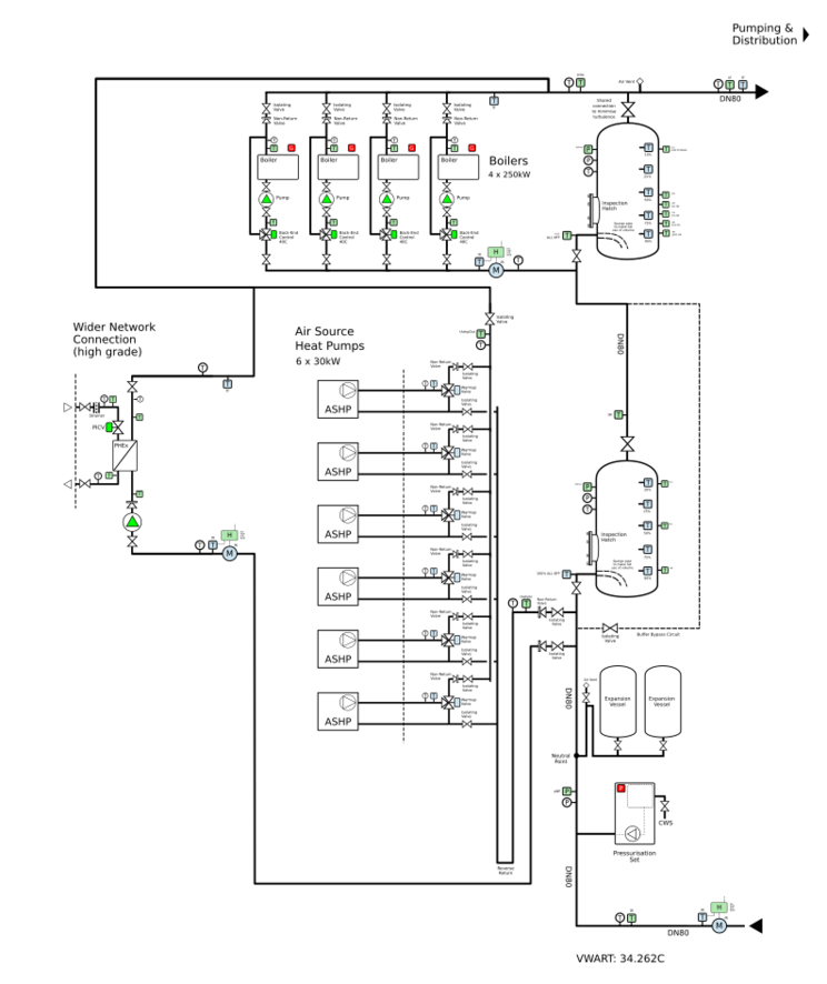
The following schematic was generated from https://hw7.ddns.net/ui/hndesign?loadCID=QmegcRKHhunR6ZR4Vvo65NEMHzau8c9CNrR1GMi7YfZT3N

Example Q&A Input
The following table is a summary of the Q&A for the bivalent system above.
| Schedule of loads [loadSchedule]
|
{table}
|
|
| Number of buildings [nBuildings]
|
1
|
buildings
|
| Peak network flow temperature [tPeak]
|
65
|
°C
|
| DHW network return temperature [tPriRtnDHW]
|
19
|
°C
|
| DHW load profile [profileDHW]
|
EST
|
|
| Central heating emitter [typeEmitter]
|
underfloor
|
|
| Central heating connection [connectionCH]
|
indirect
|
|
| External temperature at peak load [tXPeak]
|
-5
|
°C
|
| Central heating network return temperature [tPriRtnCH]
|
35
|
°C
|
| Central heating diversity [divCH]
|
70
|
%
|
| Base temperature [baseTemp]
|
16
|
|
| Central heating degree-days at base temperature [degDays]
|
1850
|
°days
|
| Boilers [goBoilers]
|
true
|
|
| Air Source Heat Pumps [goASHP]
|
true
|
|
| External Heat Network Supply [goHN]
|
true
|
|
| Water Source Heat Pumps [goWSHP]
|
false
|
|
| Cooling Source Heat Pumps [goReclaim]
|
false
|
|
| Combined Heat & Power [goCHP]
|
false
|
|
| Solar Thermal [goSolar]
|
false
|
|
| Boiler fuel type [boilerFuel]
|
gas
|
|
| Boiler Emissions [boilerEmissions]
|
0.216
|
kgCO2/kWh
|
| Available boiler outputs [listBSizes]
|
30, 50, 75, 100, 250, 500, 750, 1000
|
kW
|
| Boiler selection [selectBoilers]
|
4 x 250
|
n x kW
|
| Electrical Tariff [tariffHP]
|
flat
|
|
| Electrical Supply Emissions [elecEmissions]
|
0.233
|
kgCO2/kWh
|
| ASHP refrigerant [fridgeASHP]
|
R744
|
|
| Available heat pump outputs [listASHPSizes]
|
30
|
kW
|
| ASHP selection [selectASHP]
|
6 x 30
|
n x kW
|
| Buffer volume [vBuffer]
|
2000
|
litres
|
| Schedule of pipes sizes [pipeSizes]
|
{table}
|
|
| Flow pipe sizing maximum velocity [maxVelocity]
|
1.5
|
m/s
|
| Return pipe sizing minimum velocity [minVelocity]
|
0.5
|
m/s
|
| Save design [goSave]
|
false
|
Example Calculations
From the design above, the following calculations are arrived at:
| Total Properties
|
149
|
properties
|
| Total People
|
444
|
people
|
| Total of central heating outputs
|
603
|
kW
|
| Average people per property [pPP]
|
2.979
|
people
|
| Average people per building (density) [density]
|
444
|
people
|
| Typical HIU rating for DHW [kwDHWEst]
|
37.5
|
kW
|
| People per standard DS439 property [peepDS439]
|
2.3
|
people
|
| Equivalent number of DS439 properties [eqPropDS439]
|
193.043
|
properties
|
| Peak DHW Load [kwDS439]
|
509
|
kW
|
| Volume DHW used per property per day [vPPEST]
|
40
|
litres
|
| Volume DHW used per person per day [vPHEST]
|
28
|
litres
|
| Average temperature Rise on DHW [tRiseEST]
|
35
|
°C
|
| Volume drawn per day for DHW (tap) [vDHWEST]
|
18392
|
litres
|
| Energy used per day for DHW [kwhDHWEST]
|
751.006
|
kWh
|
| Volume used per day for DHW (primary) [vPDHW]
|
13993.913
|
litres
|
| Buffer Storage for DHW (based on 9%) [vBuffer9]
|
1259.452
|
litres
|
| Peak diversified (steady state) central heating load [kwCH]
|
422.1
|
kW
|
| Energy used per day for CH [kwhCH]
|
10130.4
|
kWh
|
| Volume used on peak load day for CH (primary) [vPCH]
|
289440
|
litres
|
| Peak energy used per day [kwhP24]
|
10881.405
|
kWh
|
| Peak volume used per day (primary) [vP24]
|
303433.913
|
litres
|
| Peak load [kwPeak]
|
931.1
|
kW
|
| Average 24h peak load [kwP24]
|
453.391
|
kW
|
| Primary flow rate at peak DHW load [m3hDHWPeak]
|
9.484
|
m3/h
|
| Primary flow rate at peak central heating load [m3hCHPeak]
|
12.06
|
m3/h
|
| Primary flow rate at peak load [m3hPeak]
|
21.544
|
m3/h
|
| Primary return temperature at peak load [tPriRtnPeak]
|
27.955
|
°C
|
| Weighted primary return temperature on peak load day [tVWART24]
|
34.262
|
°C
|
| Buffer storage peak energy content [bufferkWh]
|
86.438
|
kWh
|
| Boiler quantity [boilerQty]
|
4
|
boilers
|
| Boiler unit power [boilerkW]
|
250
|
kW
|
| Boiler peak power (n) [boilerkWPeak]
|
1000
|
kW
|
| Boiler power (n-1) [boilerkWxN1]
|
750
|
kW
|
| ASHP quantity [ASHPQty]
|
6
|
ASHPs
|
| ASHP unit power [ASHPkW]
|
30
|
kW
|
| ASHP peak power (n) [ASHPkWPeak]
|
180
|
kW
|
| ASHP power (n-1) [ASHPkWxN1]
|
150
|
kW
|
| Peak power available from all sources [kWInPeak]
|
1180
|
kW
|
| Peak power available from (n-1) sources [kWxN1]
|
930
|
kW
|
| Excess power availiable (n) [sparekW]
|
726.608
|
kW
|
| Oversizing (n) [ovsersizing]
|
160.261
|
%
|
| Oversizing (n-1) [ovsersizingN1]
|
105.12
|
%
|
| Calculated degree days per year [dDaysCalc]
|
1749.5
|
°days
|
| Peak load day degree days [dDaysPeak]
|
21
|
°days
|
| Annual days of full load heating [eqDaysPeak]
|
83.309
|
days
|
| Annual energy for central heating [kwhCH365]
|
212738
|
kWh
|
| Annual energy for domestic hot water [kwhDHW365]
|
274117
|
kWh
|
| Annual energy utilised [kwhUsed365]
|
486855
|
kWh
|
| Annual distribution heat losses (est at 20%) [kwhDistLoss365]
|
97371
|
kWh
|
| Annual energy required [kwh365]
|
584226
|
kWh
|
| Pipe bore at peak load and velocity [borePeak]
|
71.272
|
mm
|
| Nominal main line pipe size (max velocity) [dnMain]
|
DN80
|
|
| Nominal main line pipe bore [boreMain]
|
73
|
mm
|
| Velocity at peak load using nominal size [velocityPeak]
|
1.429
|
m/s
|
| Maximum pipe bore at peak load and minimum velocity [borePeakMax]
|
123.447
|
mm
|
| Maximum main line pipe size (min velocity) [dnMainMax]
|
DN100
|
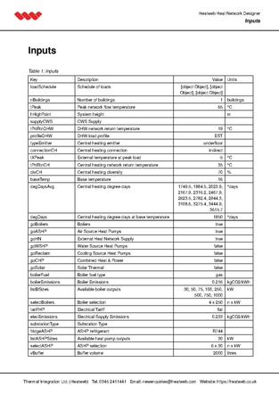
Sample PDF Designer Output
Click image to open PDF


